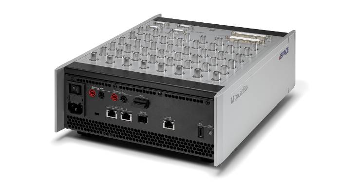
Kompakt. Leistungsstark. MicroLabBox II. Ihr Entwicklungs- und Testsystem für Rapid Control Prototyping und Hardware-in-the-Loop-Anwendungen.
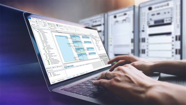
Einfacher Übergang
Von der Offline-Simulation in Simulink® zur Ausführung auf der MicroLabBox II.
Schlüsselfertige I/O-Funktionen
Umfassende I/O-Bibliotheken, die von dSPACE bereitgestellt werden.
Kommunikationsschnittstellen
Bus- und Netzwerkschnittstellen inkl. 10 GBit/s Ethernet, CAN FD, LIN.
Leistungsstarke CPU & großes FPGA
Vorbereitet auf das, was vor Ihnen liegt: Schnelle Regelkreise, komplexe Modelle und vieles mehr.
Was ist die MicroLabBox II?
Als Weiterentwicklung der bewährten MicroLabBox I ist die MicroLabBox II ein kompaktes Laborsystem für Rapid Control Prototyping und Hardware-in-the-Loop (HIL)-Anwendungen, das kompakte Größe und Kosteneffizienz mit hoher Leistung und Vielseitigkeit verbindet.
Ihr leistungsstarker Quad-Core-Prozessor kann problemlos anspruchsvolle Simulink®-Modelle ausführen, z. B. für die Simulation von Elektromotoren. Ihr umfangreicher Satz an I/O-Schnittstellen erfüllt alle Anforderungen von Steuerungs- oder Testingenieuren, die ihre Algorithmen prototypisieren wollen.
Darüber hinaus bietet die MicroLabBox II ein frei programmierbares FPGA für noch schnellere Regelkreise oder die anspruchsvollsten und genauesten Simulationsmodelle.
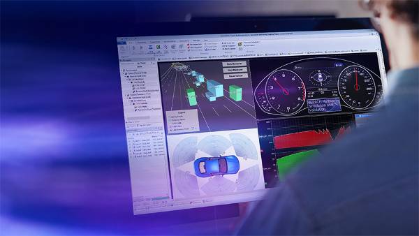
Dank der dSPACE Experimentiersoftware ControlDesk kann ohne zusätzlichen Aufwand auf Modellsignale für Visualisierungs- und Messzwecke zugegriffen werden. Die Modellparameter können während der Laufzeit kalibriert werden, ohne dass die Anwendung neu kompiliert werden muss.
Anwendungsbereiche
Mit der MicroLabBox können Sie Ihre Regel-, Test- oder Messanwendungen schnell und einfach aufbauen und eigene Regelungskonzepte umsetzen. Mehr als 100 I/O-Kanäle verschiedener Typen machen die MicroLabBox II zu einem vielseitigen System, das nicht nur in mechatronischen Forschungs- und Entwicklungsbereichen, sondern auch für alle Arten von Testzwecken eingesetzt werden kann:
- Entwicklung elektrischer Antriebe
- Entwicklung von Leistungselektronik
- Erneuerbare Energien
- Luft- und Raumfahrt
- Robotik
- Medizintechnik


Große Vielfalt an I/O-Funktionen
Als neueste Generation der bewährten MicroLabBox-Serie verfügt die MicroLabBox II über eine Vielzahl von I/O-Funktionen, die den Anschluss bestehender Modelle an Hardware-Kanäle erleichtern.
Enthaltene I/O-Funktionen:
- Voltage in / Voltage out
- PWM-Eingänge / PWM-Ausgänge
- Spannungssignalerfassung, digitale Pulserfassung
- Waveform out, Digital Pulse out
- UART, I²C 1 , SPI 1
- CAN FD, LIN
- Ethernet
- XCP on Ethernet / CAN
... und viele mehr.
1 Geplant für spätere Releases
Für E-Mobilitätsanwendungen bietet dSPACE ein umfassendes Set an sofort einsetzbaren Funktionen für prozessorbasierte E-Motor-Regelungsanwendungen einschließlich feldorientierter Regelung mit Unterstützung von Sinus-, Hall-, Inkrementalgebern oder Resolvern.
Bibliotheken für FPGA-basierte E-Motor-Steuerungsanwendungen, die noch schnellere Durchlaufzeiten ermöglichen, sind ebenfalls verfügbar.
Für Hardware-in-the-Loop-Anwendungen bietet dSPACE auch Bibliotheken für die prozessorbasierte und FPGA-basierte Simulation von Elektromotoren und Leistungselektronik.

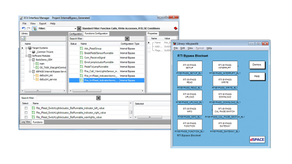
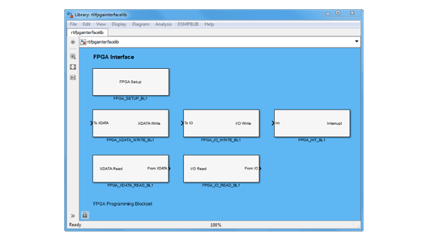
Benutzerprogrammierbares AMD® Kintex® UltraScale+ FPGA
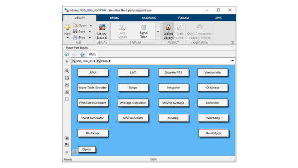
Mit den von dSPACE bereitgestellten I/O-Funktionen für schnelle Prototyping-Implementierungen können Sie Ihr eigenes Modell auf dem MicroLabBox-Prozessor ausführen oder Ihre eigene FPGA-Anwendung erstellen, die entweder modellbasiert oder in VHDL geschrieben ist. dSPACE bietet auch eine Vielzahl von Bibliotheken für die modellbasierte FPGA-Entwicklung, um von der Geschwindigkeit eines FPGAs zu profitieren, ohne sich mit den Schwierigkeiten des FPGA-Designs auseinandersetzen zu müssen.

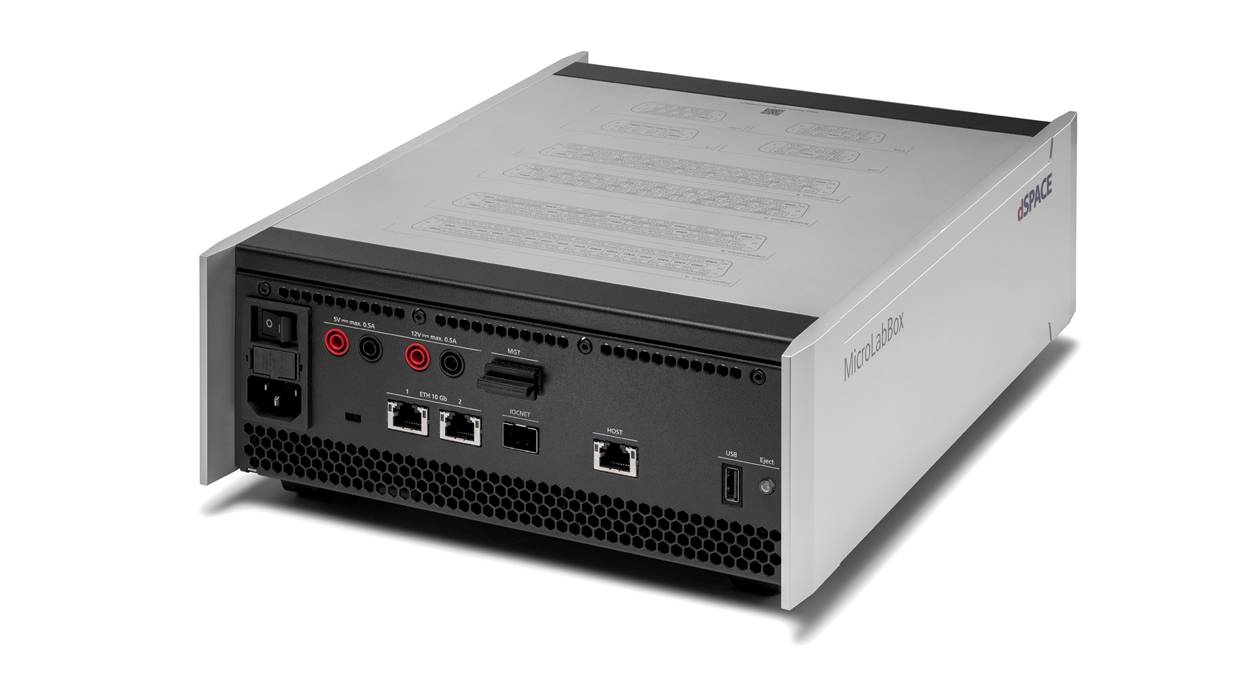
Bus-& Netzwerkschnittstellen
Die MicroLabBox II bietet bis zu 4 CAN-FD-Kanäle mit Signalverbesserungsfunktion (Signal Improvement Capability, SIC) sowie bis zu 4 LIN-Kanäle. Die beiden Standard-Ethernet-Ports unterstützen Datenraten von bis zu 10 GBit/s und können bei Verwendung eines Medienkonverters auch für Automotive Ethernet genutzt werden.

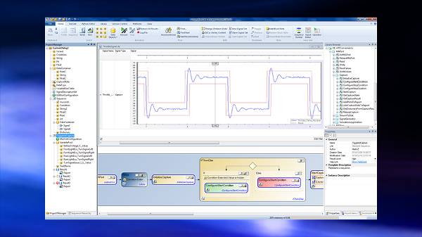
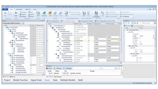
Etablierte dSPACE Werkzeugkette
Die zugehörige Software ConfigurationDesk dient der einfachen Anbindung eines bestehenden Simulink®-Modells an die Hardware-Schnittstellen der MicroLabBox II. Sobald die Schnittstellen festgelegt und konfiguriert sind, ist die Ausführung Ihres Modells nur noch einen Klick entfernt.
ConfigurationDesk ermöglicht nicht nur die Verwendung von Simulink®-Modellen, sondern unterstützt auch Container-Formate wie SIC und FMU.
Sobald die Anwendung läuft, kann ControlDesk verwendet werden, um Modellvariablen während der Laufzeit zu visualisieren, zu messen und sogar anzupassen. Der USB-Anschluss der MicroLabBox II kann auch zur Datenaufzeichnung verwendet werden.
Technische Details & Varianten

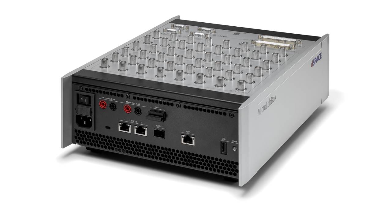
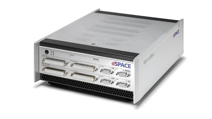
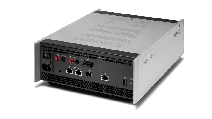
Front Panel – Einfach stapeln
Die Front-Panel-Variante ist besonders gut geeignet, wenn die MicroLabBox II in einen Schrank eingebaut wird, da die Anschlüsse von vorne zugänglich sind.
Durch die Anordnung der Anschlüsse auf der Vorderseite ist es möglich, mehrere MicroLabBoxen übereinander zu stapeln.
Darüber hinaus können Transfermodule mit geringem Aufwand angeschlossen werden, um einzelne Kabel schnell und einfach über Federzugklemmen zu stecken, ohne dass zuvor Steckverbinder konfektioniert werden müssen.

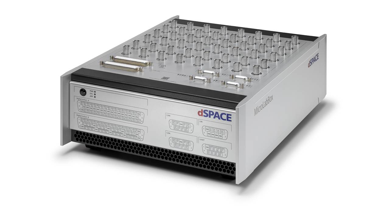
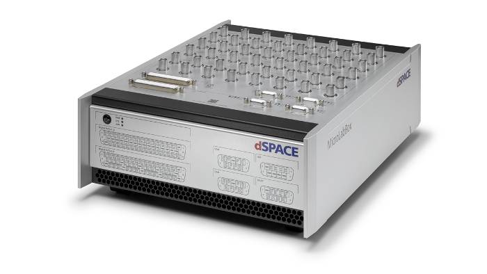
Top Panel – Benutzerdefinierte Signale
Die Top-Panel-Variante verwendet BNC-Steckverbinder für hohe Signalintegrität und ermöglicht das einfache Anschließen und Trennen einzelner Signale.
For both versions, the pin assignment of the individual connectors is printed on the housing for quick location.
Apart from the different arrangement of the connectors, the two versions are technically identical.

Advanced Feature Package
The Advanced Feature Package unlocks additional hardware and software features for more demanding use cases.
With this package, you can use 4 processor cores in total, 2 additional CAN FD channels, 4 LIN channels and IOCNET for I/O extension.
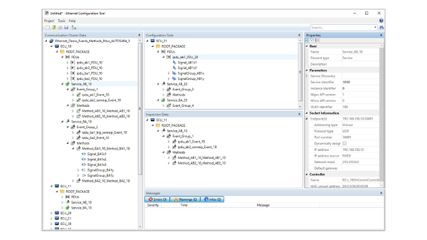
Furthermore, it enables the use of a second 10 Gb Ethernet interface and it allows you to use both interfaces with the Ethernet configuration package, e. g. to implement SOME/IP or use IEEE 802.1ad.
Our sales team is happy to advice you in chosing the rigth variant for your application!
Technical details
| Parameters | MicroLabBox II | MicroLabBox II with Advanced Feature Package | |
| Processor |
|
|
|
| FPGA |
|
||
| Communication interfaces |
|
|
|
| Analog input |
|
||
| Analog output |
|
||
| Digital I/O |
|
||
| Angular Processing Unit |
|
||
| Electric Motor Control I/O Functionality |
Functionality on digital I/O channels:
|
||
| Sensor supply |
|
||
| User feedback |
|
||
| Theft protection | Kensington® lock | ||
| Power supply & cooling |
|
||
| Operating temperature range | 0 °C … +50 °C (+32 °F … +122 °F) | ||
| Certifications |
|
||
| Parameters | Front Panel | Top Panel | |
| Connectors |
|
|
|
| Dimensions |
|
|
|
| Weight | 6.1 kg (13.5 lb) | 6.3 kg (13.9 lb) | |
1 Planned for later releases
Erforderliches Produkt
Optionale Produkte

E-Mobilitätsanwendungen

Hardware-Schnittstellen
Die MicroLabBox II bietet Hardware-Schnittstellen für Hall-, Inkremental-, Sinus-Encoder, Resolver, SSI und EnDat, die mit der optischen Schnittstelle Xilinx Aurora erweitert werden können.
Darüber hinaus verfügt die MicroLabBox II über eine integrierte Sensorversorgung mit 5-V- und 12-V-Bananensteckerausgängen. Daher ist kein zusätzliches Netzteil erforderlich, was mehr Platz auf dem Schreibtisch des Entwicklers schafft.
Profitieren Sie von den Vorteilen der FPGA-Technologie
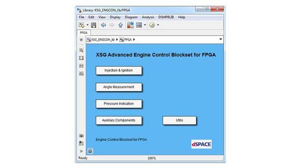
Für die hohen Schaltfrequenzen moderner Wechselrichtersteuerungen sind prozessorbasierte Ansätze oft nicht schnell genug. Deshalb bietet dSPACE FPGA-Bibliotheken an, mit denen sich FPGA-basierte Regler einfach und ohne Expertenwissen aufbauen lassen. Das gleiche Prinzip gilt für Simulationsmodelle, wobei die FPGA-Technologie höchste Dynamik und Präzision ermöglicht.


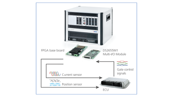
Hardware-in-the-Loop (HIL)- Anwendungen
Wie alle dSPACE Echtzeitsysteme/Plattformen kann die MicroLabBox II für eine Vielzahl von HIL-Anwendungen eingesetzt werden. Aufgrund seines kompakten Formfaktors ist er eine optimale Wahl für einen Tischsimulator, der dennoch genügend Rechenleistung und I/O für große Modelle bietet.