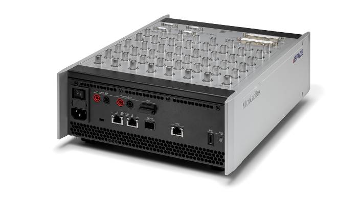
设计紧凑。功能强大。MicroLabBox II。 适合快速控制原型开发和硬件在环应用的开发和测试系统。
轻松转换
从Simulink®中的离线仿真到在MicroLabBox II上执行。
即用型I/O功能
dSPACE提供的一整套I/O库。
通信接口
总线和网络接口,包括10 GBit/s以太网、CAN FD、LIN。
CPU性能强大,FPGA庞大
为您未来的工作做好准备:快速的控制回路、复杂的模型等等。
什么是MicroLabBox II?
MicroLabBox II 是成熟的 MicroLabBox I 的进化版,,是一个紧凑型的实验室系统,适合快速控制原型开发(RCP)和硬件在环(HIL)应用。该系统设计紧凑、经济高效、性能高、用途广。
其高性能四核处理器能够轻松运行要求苛刻的Simulink®模型,用来仿真电动机等。它有各种I/O接口,可以满足控制或测试工程师对算法进行原型开发的每个要求。
此外,MicroLabBox II提供用户可编程FPGA,用于更快速的控制回路或者要求苛刻的精准仿真模型。
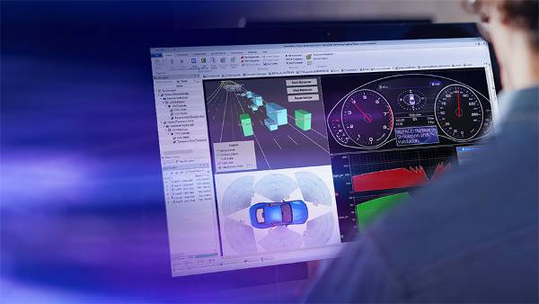
借助dSPACE实验软件ControlDesk,可以访问模型信号进行可视化和测量,无需额外的工作。运行时可以校准模型参数,无需重新编译应用程序。
应用领域
MicroLabBox II能够快速简单地设置控制、测试或测量应用程序,并帮助您将各个概念变成现实。MicroLabBox II有100多个不同类型的输入/输出通道,因而是一个多功能系统,不仅可用于机电一体化研发领域,还可用于各种测试,例如:
- 电力驱动开发
- 电力电子开发
- 可再生能源
- 航空航天
- 机器人
- 医学工程


多种I/O功能
作为成熟的MicroLabBox系列的新一代产品,MicroLabBox II具有多种I/O功能,可以轻松地将现有模型连接至硬件通道。
所含I/O功能:
- 电压输入/电压输出
- PWM输入/PWM输出
- 电压信号捕获、数字脉冲捕获
- 波形输出、数字脉冲输出
- UART,I²C 1 ,SPI 1
- CAN FD、LIN
- 以太网
- 以太网/CAN上的XCP
等等。
1 计划稍后发布
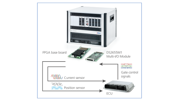
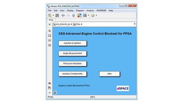
对于 电动出行应用 ,dSPACE推出了一整套即用型功能,适合基于处理器的电动机控制应用(包括磁场定向控制),支持正弦编码器、霍尔编码器、增量编码器或解析器。
针对基于FPGA的电动机控制应用库还可以加快周转。
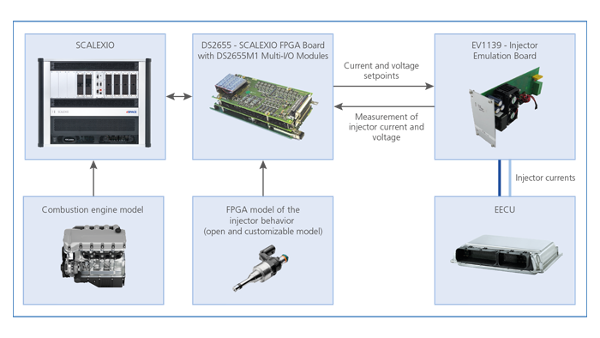
对于硬件在环应用,dSPACE还提供了各种库用于基于处理器和基于FPGA的电动机及电力电子仿真。

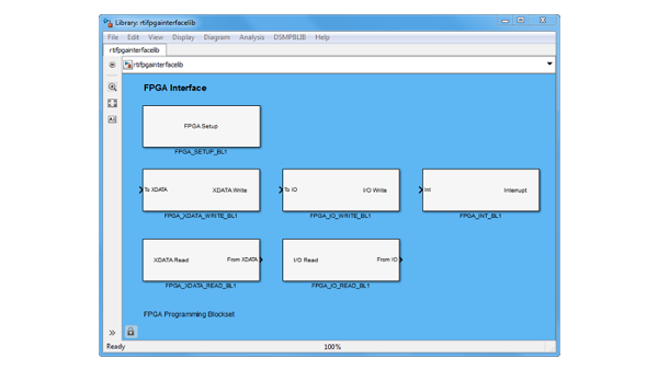
用户可编程AMD® Kintex® UltraScale+ FPGA
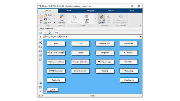
使用dSPACE为快速实现原型开发提供的I/O功能,您可以在MicroLabBox处理器上执行您自己的模型,也可以创建自己的FPGA应用程序(基于模型还是用VHDL编写)。dSPACE还会为基于模型的FPGA开发提供各种库,尽享FPGA的速度,无需应对FPGA设计的难题。

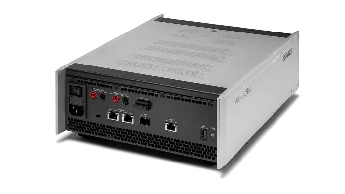
总线和网络接口
MicroLabBox II可提供4个具有信号改善功能(SIC)的CAN FD通道,还可提供4个LIN通道。两个标准以太网端口支持高达10 GBit/s的数据速率,使用媒体转换器时还可以用于车载以太网。

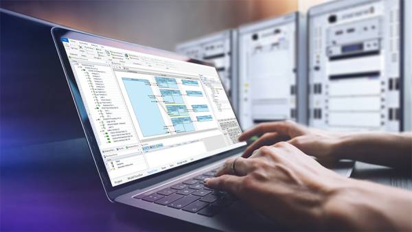
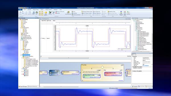
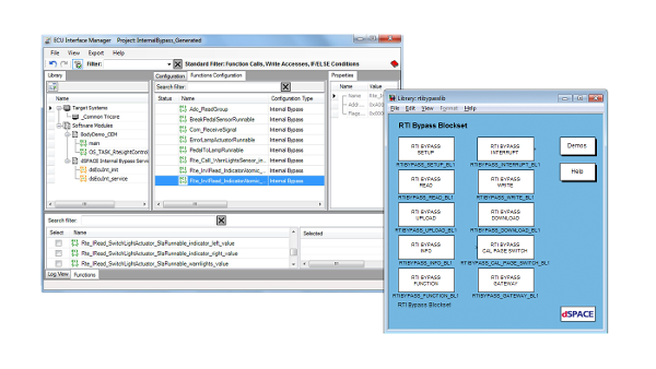
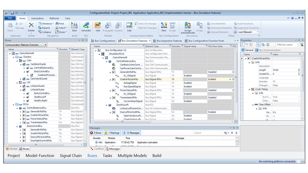
完善的dSPACE工具链
相应软件ConfigurationDesk用于将现有Simulink®模型轻松连接至MicroLabBox II的硬件接口。指定并配置接口后,只需点击一下即可执行您的模型。
ConfigurationDesk不仅可以使用Simulink®,还支持SIC和FMU等容器格式。
应用程序运行时,可以在运行过程中使用ControlDesk可视化、测量,甚至调整模型变量。MicroLabBox II USB端口还可用于数据记录。
技术细节和不同版本

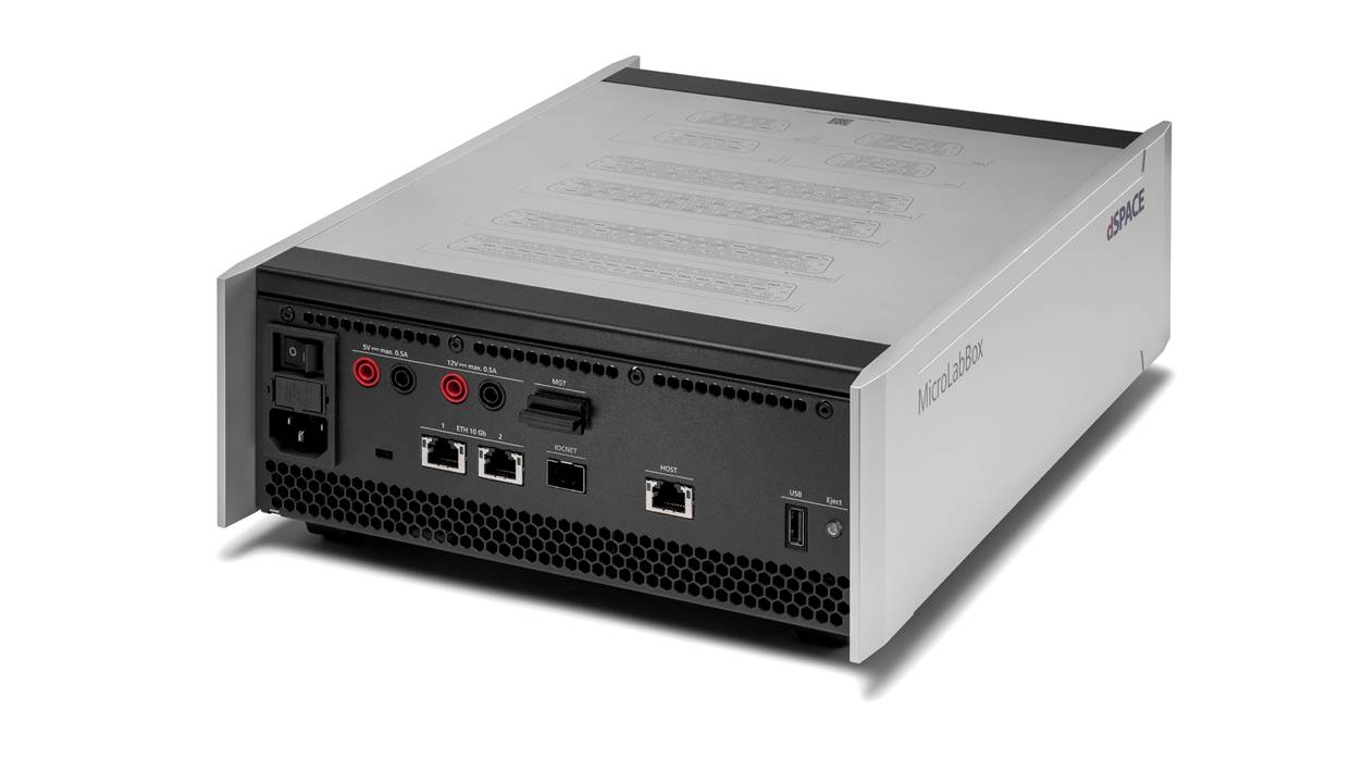
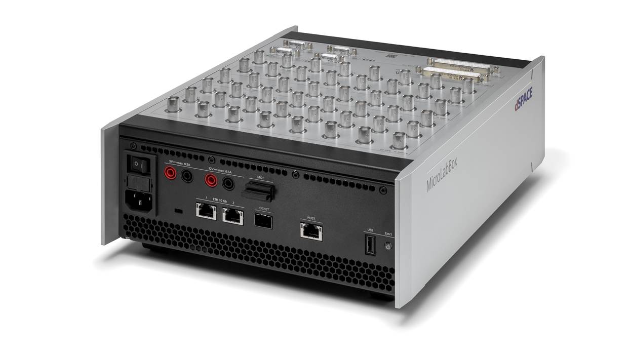
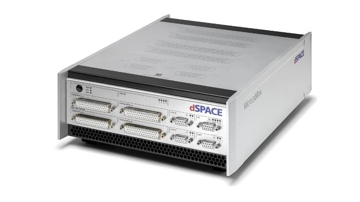
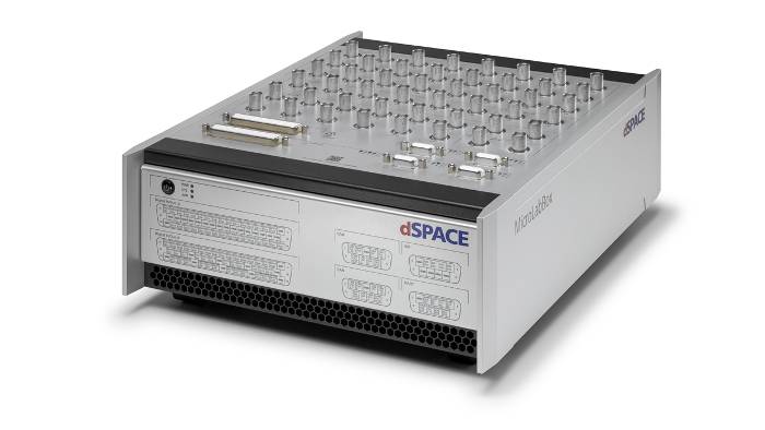
前面板 - 方便堆叠
如果机柜中装有MicroLabBox II,特别适合使用前面板型,这样就可以从正面查看连接器。
由于连接器布置在正面,可以堆叠若干MicroLabBoxes。
此外,可以轻松连接传输模块,使用回拉式弹簧端子即可快速轻松地插入各条电缆,无需事先组装连接器。

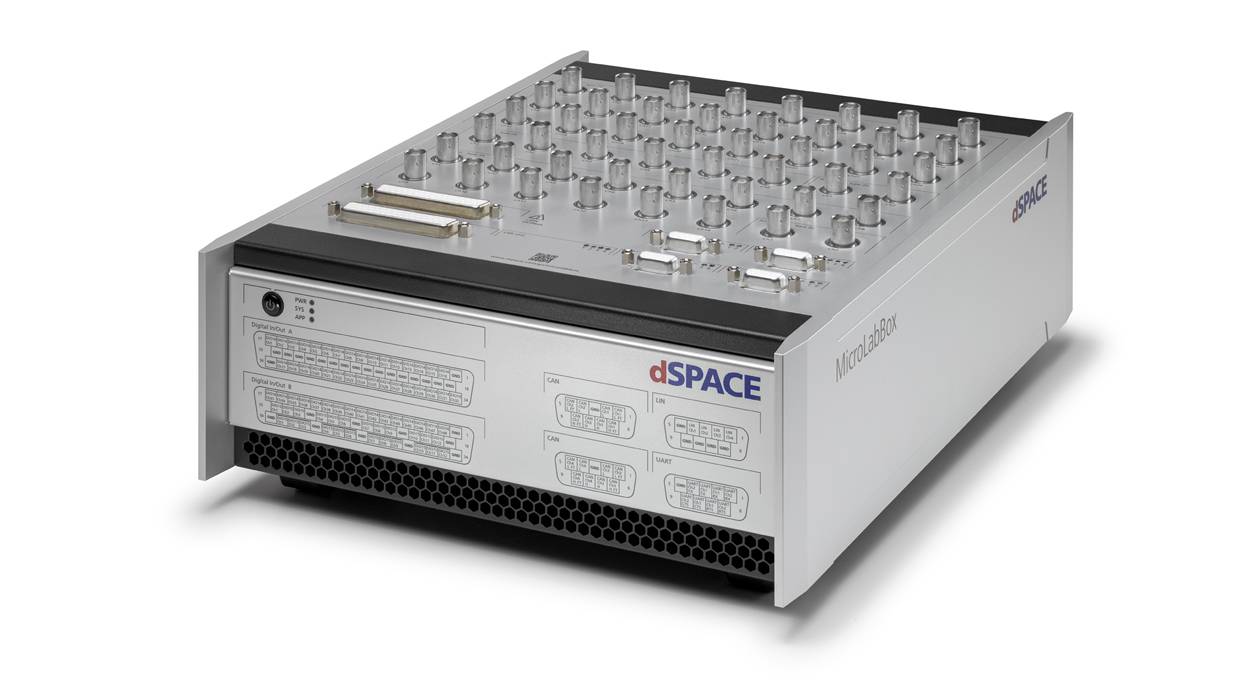
For both versions, the pin assignment of the individual connectors is printed on the housing for quick location.
Apart from the different arrangement of the connectors, the two versions are technically identical.

Advanced Feature Package
The Advanced Feature Package unlocks additional hardware and software features for more demanding use cases.
With this package, you can use 4 processor cores in total, 2 additional CAN FD channels, 4 LIN channels and IOCNET for I/O extension.
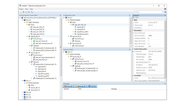
Furthermore, it enables the use of a second 10 Gb Ethernet interface and it allows you to use both interfaces with the Ethernet configuration package, e. g. to implement SOME/IP or use IEEE 802.1ad.
Our sales team is happy to advice you in chosing the rigth variant for your application!
Technical details
| Parameters | MicroLabBox II | MicroLabBox II with Advanced Feature Package | |
| Processor |
|
|
|
| FPGA |
|
||
| Communication interfaces |
|
|
|
| Analog input |
|
||
| Analog output |
|
||
| Digital I/O |
|
||
| Angular Processing Unit |
|
||
| Electric Motor Control I/O Functionality |
Functionality on digital I/O channels:
|
||
| Sensor supply |
|
||
| User feedback |
|
||
| Theft protection | Kensington® lock | ||
| Power supply & cooling |
|
||
| Operating temperature range | 0 °C … +50 °C (+32 °F … +122 °F) | ||
| Certifications |
|
||
| Parameters | Front Panel | Top Panel | |
| Connectors |
|
|
|
| Dimensions |
|
|
|
| Weight | 6.1 kg (13.5 lb) | 6.3 kg (13.9 lb) | |
1 Planned for later releases
必需产品
选用产品


电动出行应用

硬件接口
MicroLabBox II 提供霍尔、增量、正弦编码器、旋转变压器、SSI 和 EnDat 硬件接口,可通过 Xilinx Aurora 光学接口进行扩展。
此外,MicroLabBox II还配备一个集成式传感器电源,采用5 V和12 V香蕉插头输出。因此,无需额外的电源,这给开发人员的办公桌留出了更多的空间。