Compacte. Puissante. MicroLabBox II. Votre système de test et de développement pour les applications de prototypage rapide de lois de commande et Hardware-In-the-Loop.
Transition simple
De la simulation offline dans Simulink® à l’exécution sur la MicroLabBox II.
Fonctions d’E/S prêtes à l’emploi
Ensemble complet de bibliothèques d’E/S fournies par dSPACE.
Interfaces de communication
Interfaces bus et réseau, y compris Ethernet 10 Gbit/s, CAN FD, LIN.
Ordinateur puissant et grand FPGA
Conçu pour ce qui vous attend : Boucles de commande rapides, modèles complexes et bien plus encore.
Qu’est-ce que la MicroLabBox II ?
Evolution de la MicroLabBox I qui est largement utilisée, la MicroLabBox II est un système de laboratoire compact pour les applications de prototypage rapide de lois de commande et HIL (Hardware-In-the-Loop), qui combine taille compacte et excellent rapport coût/efficacité avec des performances élevées et une forte polyvalence.
Son processeur quatre coeurs hautes performances peut facilement exécuter des modèles Simulink® exigeants, par exemple pour la simulation de moteurs électriques. Son vaste ensemble d’E/S s’interface avec chaque exigence d'ingénieurs de contrôle ou de test qui veulent prototyper leurs algorithmes.
En outre, la MicroLabBox II fournit un FPGA programmable par l'utilisateur pour des boucles de contrôle encore plus rapides ou les modèles de simulation les plus exigeants et précis.
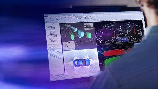
Grâce au logiciel d’expérimentation dSPACE, ControlDesk, les signaux du modèle sont accessibles à des fins de visualisation et de mesure sans effort supplémentaire. Les paramètres du modèle peuvent être calibrés pendant l’exécution sans recompiler l'application.
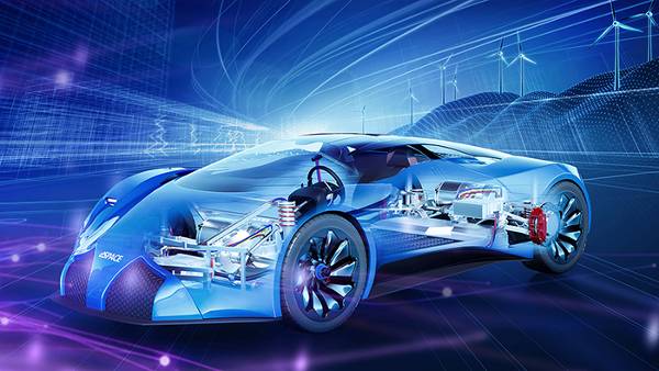
Domaines d’application
La MicroLabBox vous permet de configurer rapidement et simplement vos applications de contrôle, de test ou de mesure et vous aide à concrétiser vos concepts individuels. Plus de 100 canaux E/S de différents types font de la MicroLabBox II un système polyvalent qui peut être utilisé non seulement dans les domaines de recherche et développement mécatroniques, mais aussi à des fins de test dans les domaines suivants :
- Développement de machines électriques
- Développement de l’électronique de puissance
- Energies renouvelables
- Aéronautique
- Robotique
- Ingénierie médicale


Grande variété de fonctions d’E/S
En tant que dernière génération de la série MicroLabBox bien établie, la MicroLabBox II est livrée avec une grande variété de fonctions d’E/S qui permettent de connecter facilement les modèles existants aux canaux matériels.
Fonctions d’E/S incluses :
- Tension en entrée/tension en sortie
- Entrées PWM / sorties PWM
- Capture de signal de tension, capture d’impulsion numérique
- Forme d’onde en sortie, impulsion numérique en sortie
- UART, I²C 1 , SPI 1
- CAN FD, LIN
- Ethernet
- XCP sur Ethernet/CAN
... et plus encore.
1 Prévu pour les versions ultérieures
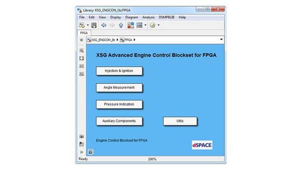
Pour les applications d’e-mobilité , dSPACE offre un ensemble complet de fonctions prêtes à l’emploi pour les applications de contrôle des moteurs électriques basées sur processeur, y compris le contrôle par champ avec le support des encodeurs ou des résolveurs sinusoïdaux, hall et incrémentaux.
Des bibliothèques pour les applications de commande de moteur électrique basées sur FPGA qui permettent d'atteindre des temps de rotation encore plus rapides sont également disponibles.
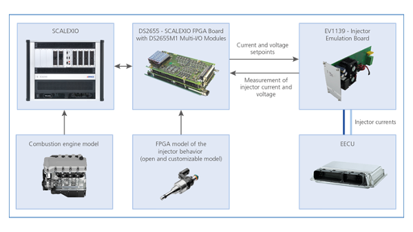
Pour les applications Hardware-In-The-Loop, dSPACE fournit également des bibliothèques pour la simulation de moteur électrique et d'électronique de puissance basée sur processeur et FPGA.

FPGA AMD® Kintex® UltraScale+ programmable par l’utilisateur
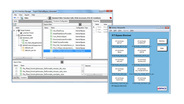
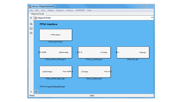
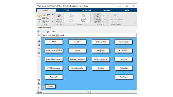
En utilisant les fonctions d’E/S fournies par dSPACE pour des mises en œuvre rapides de prototypage, vous pouvez exécuter votre propre modèle sur le processeur MicroLabBox ou vous pouvez créer votre propre application FPGA, basée sur modèle ou écrite en VHDL. dSPACE fournit également une variété de bibliothèques pour le développement de FPGA basé sur modèle pour bénéficier de la vitesse d'un FPGA sans avoir à traiter les difficultés de la conception FPGA.

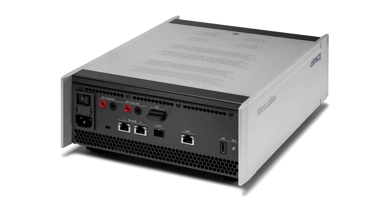
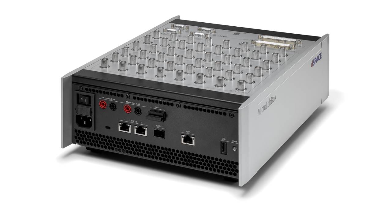
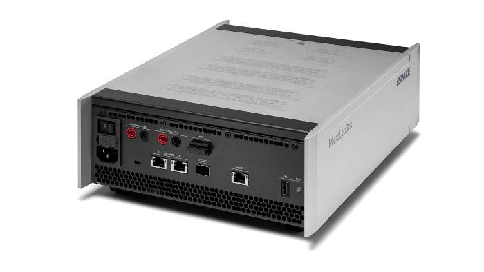
Interfaces bus et réseau
La MicroLabBox II fournit jusqu'à 4 canaux CAN FD avec capacité d'amélioration du signal (SIC) ainsi que jusqu'à 4 canaux LIN. Les deux ports Ethernet standard supportent des débits de données allant jusqu'à 10 Gbit/s et peuvent également être utilisés pour l'Ethernet automobile avec un convertisseur de média.

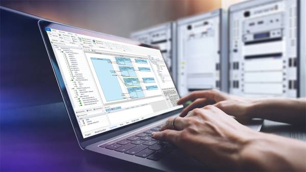
Chaîne d’outils dSPACE largement utilisée
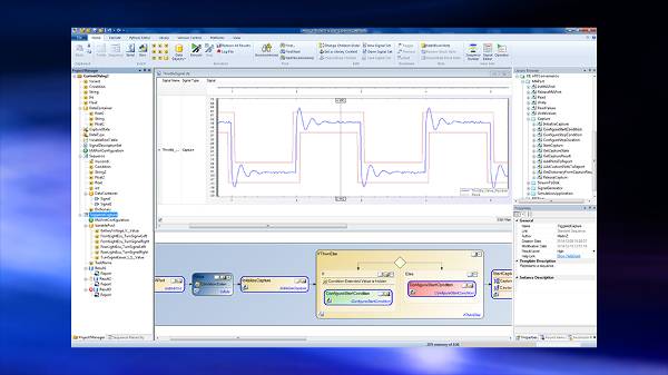
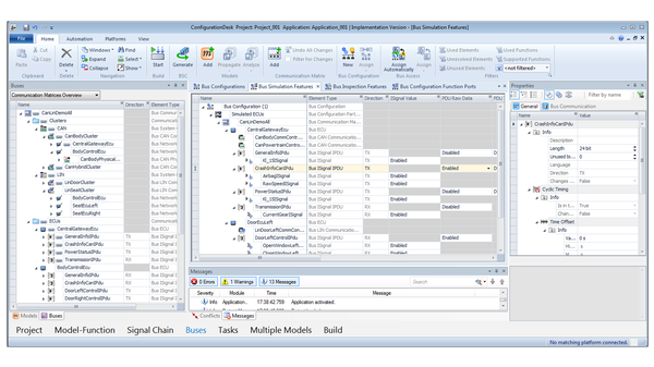
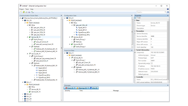
Le logiciel ConfigurationDesk correspondant permet de connecter facilement un modèle Simulink® existant aux interfaces matérielles de la MicroLabBox II. Dès que les interfaces sont spécifiées et configurées, l’exécution de votre modèle n’est qu’à un clic.
ConfigurationDesk vous permet non seulement d'utiliser des modèles Simulink®, mais supporte également des formats de conteneur tels que SIC et FMU.
Une fois que l’application est en cours d’exécution, ControlDesk peut être utilisé pour visualiser, mesurer et même ajuster les variables du modèle pendant l’exécution. Le port USB de la MicroLabBox II peut également être utilisé pour l’enregistrement des données.
Détails techniques et variantes

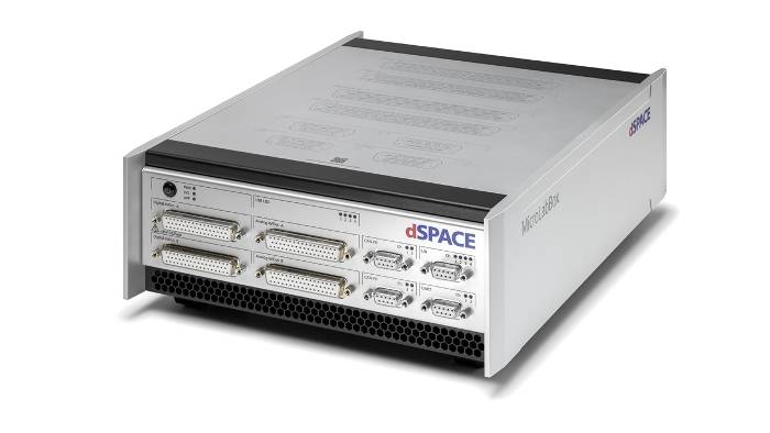
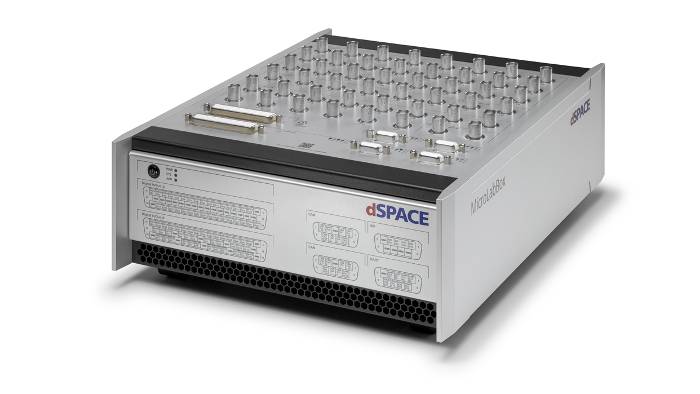
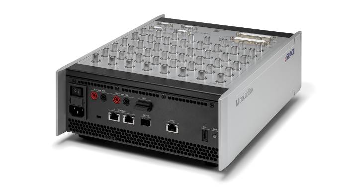
Panneau frontal - Empilez simplement
La variante à panneau frontal est particulièrement bien adaptée si la MicroLabBox II est installée dans une armoire car les connecteurs sont accessibles depuis la face avant.
En raison de la disposition des connecteurs sur la face avant, il est possible d’empiler plusieurs MicroLabBox les unes sur les autres.
En outre, les modules de transfert peuvent être connectés sans effort afin de brancher rapidement et facilement des câbles individuels avec des terminaux spring cage sans avoir à assembler les connecteurs au préalable.

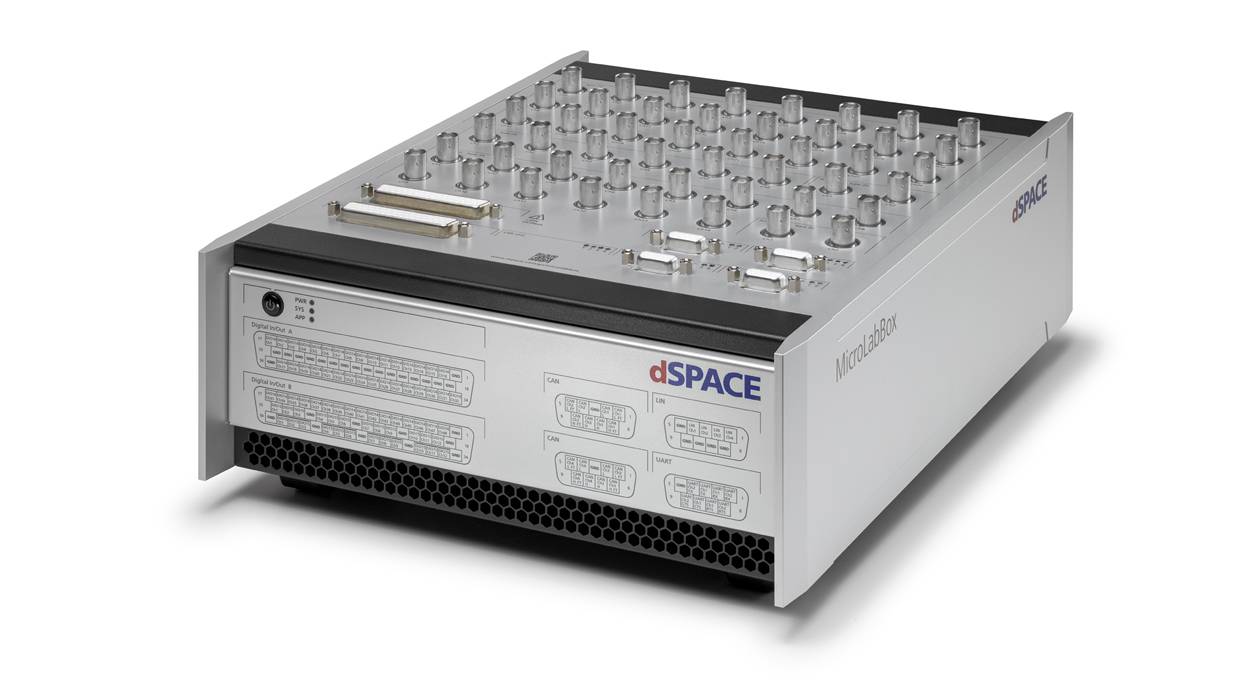
Panneau supérieur - Signaux personnalisés
La variante à panneau supérieur utilise des connecteurs BNC pour une intégrité élevée des signaux et permet une connexion et une déconnexion faciles des signaux individuels.
For both versions, the pin assignment of the individual connectors is printed on the housing for quick location.
Apart from the different arrangement of the connectors, the two versions are technically identical.

Advanced Feature Package
The Advanced Feature Package unlocks additional hardware and software features for more demanding use cases.
With this package, you can use 4 processor cores in total, 2 additional CAN FD channels, 4 LIN channels and IOCNET for I/O extension.
Furthermore, it enables the use of a second 10 Gb Ethernet interface and it allows you to use both interfaces with the Ethernet configuration package, e. g. to implement SOME/IP or use IEEE 802.1ad.
Our sales team is happy to advice you in chosing the rigth variant for your application!
Technical details
| Parameters | MicroLabBox II | MicroLabBox II with Advanced Feature Package | |
| Processor |
|
|
|
| FPGA |
|
||
| Communication interfaces |
|
|
|
| Analog input |
|
||
| Analog output |
|
||
| Digital I/O |
|
||
| Angular Processing Unit |
|
||
| Electric Motor Control I/O Functionality |
Functionality on digital I/O channels:
|
||
| Sensor supply |
|
||
| User feedback |
|
||
| Theft protection | Kensington® lock | ||
| Power supply & cooling |
|
||
| Operating temperature range | 0 °C … +50 °C (+32 °F … +122 °F) | ||
| Certifications |
|
||
| Parameters | Front Panel | Top Panel | |
| Connectors |
|
|
|
| Dimensions |
|
|
|
| Weight | 6.1 kg (13.5 lb) | 6.3 kg (13.9 lb) | |
1 Planned for later releases
Produit requis
Produits optionnels

Applications d’e-mobilité

Interfaces matérielles
La MicroLabBox II fournit des interfaces matérielles pour Hall, Incrémental, encodeur sinusoïdal, résolveur, SSI et EnDat qui peuvent être étendues avec l'interface optique Xilinx Aurora.
De plus, la MicroLabBox II dispose d’une alimentation de capteur intégrée avec des fiches bananes de 5 V et 12 V. Par conséquent, il n'y a pas d'alimentation électrique supplémentaire nécessaire, ce qui qui laisse plus de place sur le bureau du développeur.
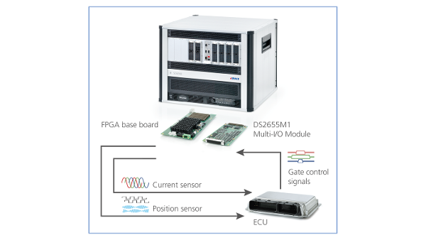
Tirer parti des avantages de la technologie FPGA
Pour les hautes fréquences de commutation des contrôleurs de convertisseur de pointe, les approches basées sur les processeurs ne sont souvent pas assez rapides. Par conséquent, dSPACE propose des bibliothèques FPGA pour vous permettre de créer facilement des contrôleurs basés sur FPGA sans avoir besoin de connaissances expertes. Le même principe s'applique aux modèles de simulation, où la technologie FPGA permet une dynamique et une précision maximales.


Applications Hardware-In-the-Loop (HIL)
Comme tous les systèmes/toutes les plates-formes en temps réel dSPACE, la MicroLabBox II peut être utilisée pour diverses applications HIL. En raison de son format compact, c'est un choix optimal pour un simulateur sur table, qui fournit également assez de puissance de calcul et d’E/S pour les grands modèles.