Validating code for electronic control units (ECUs) by means of a software-in-the-loop (SIL) simulation has become an integral part of ECU development in the automotive sector. Whereas a few years ago it was more common to test subsystems, today the simulation of the entire system is becoming increasingly important. One reason for this is the increasing level of networking and the associated dependencies between the ECUs. Overall simulations are particularly important for original equipment manufacturers (OEMs) – suppliers typically provide the virtual ECUs (V-ECUs) required for this. When it comes to collaboration, OEMs are often faced with the question: What do I have to do to get the right V-ECU for the overall simulation from the supplier?
The Solution: A Standard for V-ECUs
The Functional Mock-up Interface (FMI) standard is available for exchanging simple V-ECUs in early development phases. For more complex V-ECUs, however, this standard is not sufficient, especially if these include a bus interface. That is why the FMI Layered Standard Network Communication project is working intensively on a new standard that enables efficient exchange between partners for such V-ECUs. The advantages for validation are obvious:
- Lower integration costs thanks to better interoperability of tools and test platforms
- More efficient collaboration thanks to significantly reduced coordination effort between OEMs and suppliers
Read all about the current development status of the standard and how dSPACE will support it in the future.
FMI 3.0 and the Layered Standard Concept
The FMI standard is already widely used in the field of simulation models and makes collaboration between OEMs and suppliers much easier. In version 3.0, a number of features have been added to create the basis for using it for more complex V-ECUs in the future, including:
- Clock variables that enable the triggering of events
- Terminals which allow for grouping input/output variables
- The Layered Standard Concept
The latter allows new features to be added to the existing FMI standard without changing the original standard.

FMI Layered Standard Network Communication
Since mid-2022, dSPACE has been significantly supporting the activities related to FMI Layered Standard Network Communication and contributing its many years of experience in the field of bus simulation. The focus is always on acceptance of the new standard by all parties involved, i.e., OEMs, suppliers, and tool vendors.
The project recently reached a first important milestone: the "alpha" release, the first version of the standard for CAN bus simulation. This step was so important because V-ECUs can now be tested and exchanged between the development partners on this basis. Work is underway on other buses such as LIN, Ethernet, and FlexRay, so the first versions will also be available here shortly.
The work results are transparent and can be viewed online by everyone.

The Right Interface for Every V-ECU
A prerequisite for the acceptance of a standard is its applicability for relevant use cases. These can vary greatly for V-ECUs and typically depend on the level of the V-ECU. If the V-ECU levels are classified from 0 to 4 as in the prostep ivip white paper Requirements for the Standardization of V-ECUs, a bus interface becomes relevant from level 2, for example.
While level 0 and level 1 V-ECUs could already be created and exchanged on the basis of FMI, the new standard FMI Layered Standard Network Communication is required from level 2 onwards. To sum it up: No matter what type of V-ECUs with bus interface you want to create or exchange – the new standard will provide a suitable, standardized interface.
Good to Know
The level of a V-ECU provides information about its development status. When it comes to simulation, the following applies: The further the development of the V-ECU progresses, the more details have to be taken into account.
- Level 0 and level 1: In the early phases of development, the focus is on validating individual application components. The exact type of signal transmission between V-ECUs is secondary and is usually not yet fully specified.
- From level 2: Bus communication and the integration of the V-ECU into an overall simulation are becoming increasingly important. From here, basic software for bus communication must be integrated into the V-ECU. For easier integration and faster creation of the V-ECU, simplified basic software that only includes the communication (COM) module is usually used in earlier development phases.
- Level 3: These V-ECUs come very close to the real ECU and ideally only differ in terms of the hardware-dependent driver modules. All basic software located above these modules is part of the test object here and is therefore fully integrated into the V-ECU.
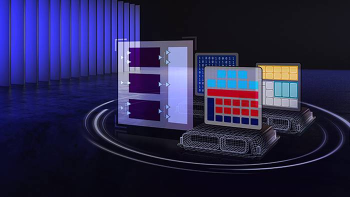
Physical Signal Abstraction
If simplified basic software, which only includes the communication (COM) module, is used for level 2 V-ECUs, this is colloquially referred to as high cut, as only the upper layer of the software is included in the V-ECU. The FMI Layered Standard Network Communication provides the so-called Physical Signal Abstraction as an interface for the creation of such V-ECUs. This interface focuses on the transmission of the individual bus signals and the time of the transmission.
Network Abstraction
With level 3 V-ECUs, the entire basic software above the Controller Area Network (CAN) driver module is usually integrated into the V-ECU. The cut in the software is therefore at a very low level, usually in the hardware-dependent driver modules, which is referred to as a low cut. The new layered standard also defines a suitable interface for this with the Network Abstraction. Here, the transmission does not take place at bus signal level, but on the basis of the associated frames/PDUs (protocol data units).
The Network Abstraction develops its full potential in conjunction with an additional bus simulation. This makes it possible to include the timing and prioritization of bus messages as well as error states during the transmission of frames/PDUs in the simulation. The integrated basic software can thus be tested very realistically.
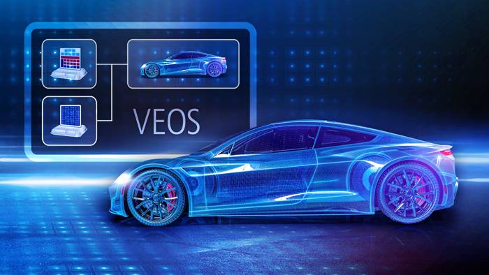
In this context, it is particularly convenient for the user, if the simulation platform provides the bus simulation directly as an integrated feature. This is where VEOS comes into play: The dSPACE platform for PC-based simulation already includes the required bus simulation, making it much easier for users to set up the simulation system.

Which interface is the right one for my use case?
A bus simulation at the Physical Signal Abstraction layer is particularly suitable in these cases:
- Level 2 V-ECUs in early phases
- The other simulation participants provide network signals exclusively in the form of physical signals.
- A cut within the V-ECU at the level of the communication (COM) module is possible and the granularity of the simulation is acceptable.
In a bus simulation at the Network Abstraction layer, network signals are exchanged on the basis of the associated frames. The basic software can therefore be cut starting from the PDU Router (PduR) module level down to the hardware level. This layer is thus suitable in the following cases:
- Level 2 and level 3 V-ECUs that contain basic software below the COM module
- Other simulation participants, e.g., restbus models, provide bus messages based on frames/PDUs.
- Simulation of the bus behavior is desired or necessary.
Creation and Simulation of V-ECUs with dSPACE
The new layered standard also plays a key role at dSPACE, especially in the area of SIL simulation. Support for the standard is currently being implemented step by step in the dSPACE tools – initially for SystemDesk, the dSPACE tool for generating V-ECUs, and for VEOS, the platform for PC-based simulation.
Users who already work with the tools can continue to use them in their usual form and enjoy these additional features:

SystemDesk
MCAL modules for the bus drivers can also be integrated into V-ECUs in future if they subsequently need to be exported as FMUs (*.fmu). Until now, this was only possible with V-ECUs in conjunction with the dSPACE-proprietary *.vecu format. This means that V-ECUs can be created on the basis of FMI3 and the Network Abstraction of the layered standard.

VEOS
The simulation platform will automatically recognize FMUs with FMI Layered Standard Network Communication based on Network Abstraction during import. In this context, VEOS does not display bus terminals as variables or ports, but as bus controllers as usual. Restbus simulations in the form of bus simulation containers (BSC) can still be connected directly to V-ECUs. VEOS will also support the simulation of bus behavior as usual.
What will be the next steps?
With the alpha release of the layered standard for CAN, the FMI working group has reached a first important milestone. In addition to the actual specification, first demos, a C-API, and How To documentation for creating FMUs with CAN bus are already available and publicly accessible. Cross-checks are currently being carried out to ensure interchangeability between tool manufacturers and to eliminate any final inconsistencies in the specification.
At the same time, the group is working on the specification for other buses such as FlexRay. A first draft is already available for LIN. As the basic principles are the same for all bus types, the working group can draw on the findings from the CAN specification, which speeds up the process considerably. dSPACE will also continue to be heavily involved in this area.
As far as the dSPACE tools are concerned, the implementation and support of the layered standard is in full swing: SystemDesk and VEOS will start with CAN, other dSPACE tools and support for other buses will follow.
About the Authors

Markus Süvern
Team Lead, Production Software & SIL Simulation, dSPACE GmbH

Christian Becker
Product Manager, Production Software & SIL Simulation, dSPACE GmbH