The scalable dSPACE solution for BMS testing provides developers of battery management systems with best-in-class battery cell emulation and real-time-capable battery models that fit any use case. Our BMS test equipment is used in a wide range of industries, including automotive, aerospace, rail, off-highway, and energy. Get an overview of our BMS test solution and learn how your development process will benefit from it.
Why choose dSPACE for BMS tests?
Whether you are working on battery systems for mobile or stationary applications, we offer a powerful solution for testing the battery management systems required for state-of-the-art batteries, both on the signal level and on the high-voltage level.
With its outstanding performance and precision, our BMS test equipment can be used for various applications in different industries and can support you in validating the functionality of cutting-edge battery management systems, while enabling you to be well-prepared for future challenges. With an overall system voltage of up to 1,500 V, our modular and finely-scalable test solution can be tailored to any kind of battery system.
Highlights of Our BMS Testing Solution
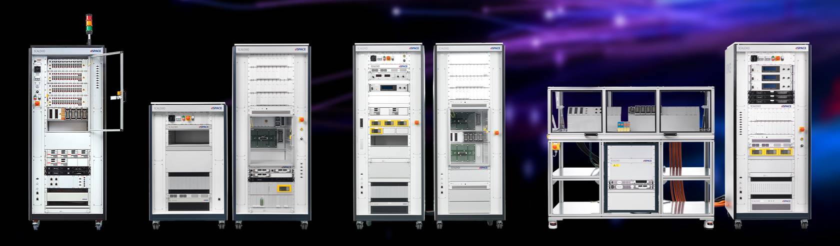
- Modular and scalable system architecture fits any use case
- Best-in-class battery cell emulation with outstanding precision
- Ready-to-use, real-time-capable battery model
Demo Video: Next-Level BMS Testing
Watch this video and learn how to test your battery management system with dSPACE expertise. Discover:
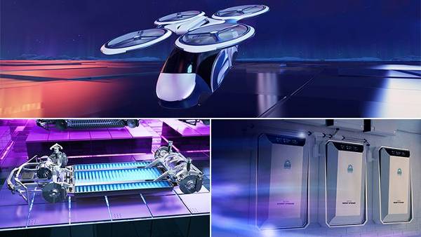
- Why our BMS test equipment is able to cover a wide range of use cases, including electric vehicle batteries, electric aircraft applications, and stationary storage systems
- What scalable and flexible BMS testing means
- How to test the cell balancing of a BMS unit
Interested in an individual demonstration?

dSPACE Solution for BMS Testing on the Signal Level
Testing a BMS on the signal level means testing its main functions and its interaction with the vehicle network or any other environment without using high voltages. For this purpose, the battery cells and the cell supervision circuits (CSCs) are simulated.
For the simulation of CSCs and additional components, such as current sensors, you can use our SCALEXIO real-time hardware. Especially for the communication between the simulated CSCs and the device under test (DUT), our test system supports a wide range of communication interfaces, including CAN, SPI, isoSPI, UART, and I²C.

dSPACE Solution for BMS Testing on the High-Voltage Level
Testing a BMS on the high-voltage level means testing the complete BMS, including one or all CSC modules. This kind of testing is essential for release and acceptance tests, and highly relevant for the automotive-specific functional safety standard ISO 26262.
For testing battery management systems on the high-voltage level, we provide a powerful test system that emulates all inputs of the BMS. This includes all battery cell voltages, temperature sensors, and the battery current as well as all signals coming from the various high-voltage sensors in the vehicle, e.g., the sensors at the inverter, the battery, or the charging point.
Key Benefits of the dSPACE BMS Testing Solution
- Seamless integration of signal and voltage level testing
- Overall system voltage of up to 1,500 V
- High accuracy thanks to our high-precision battery cell voltage emulation boards
- Current sensor stimulation with real currents of several hundred amperes
- Integrated electrical failure simulation of open wires, short circuits, and high-frequency ripple voltages
- Sophisticated safety concept with a central safety controller to supervise the entire test system
- Compact and modular test system using 19” 3-U slot units
- Large safety compartment for the DUT
- Short wiring harness from the test system to the DUT
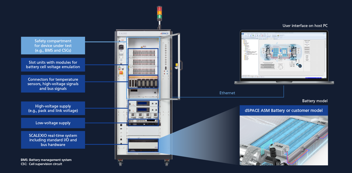
General Structure of a dSPACE BMS Test System
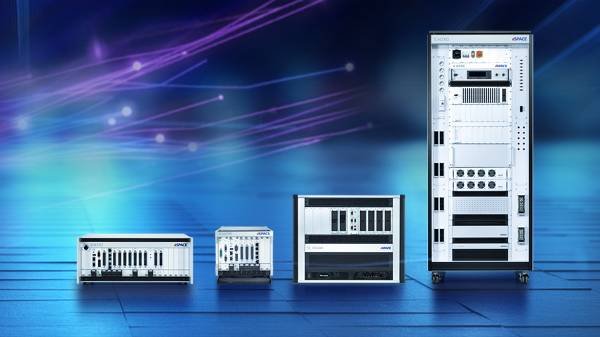
The core of our BMS testing solution is the SCALEXIO Battery HIL. The SCALEXIO Battery HIL comes as a predefined or customizable system based on one or more 19'' racks, including a SCALEXIO real-time system, standard I/O and bus hardware, as well as a scalable number of:
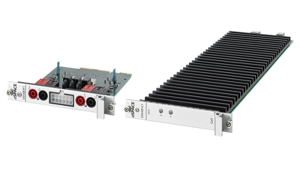
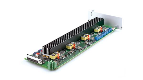
- Cell emulation boards for high-precision battery voltage emulation
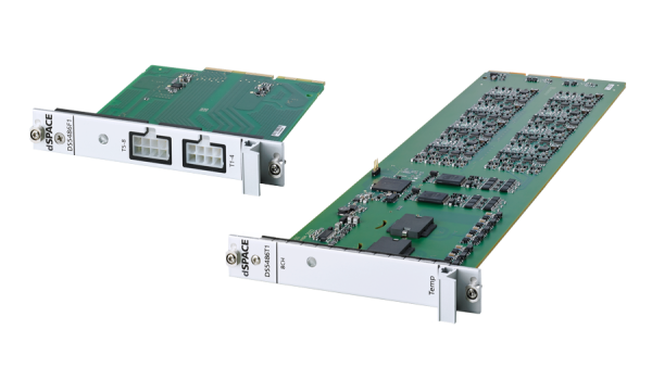
- Temperature sensor emulation channels
- High-voltage sensor simulations
To ensure safe operation, the SCALEXIO Battery HIL has an integrated safety compartment to store the system under test and to protect the test engineers and the equipment against high voltages. Thanks to its modular design using stackable 19” slot units, our test system is highly scalable and can be easily adapted to individual project requirements.
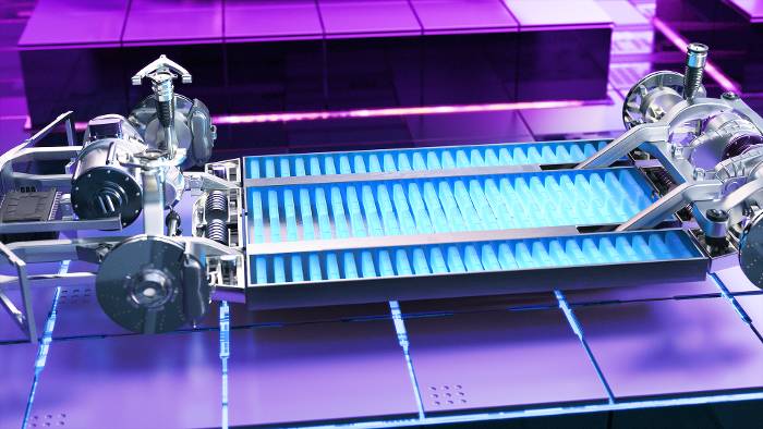
Modeling the Battery
On the software side, our ASM Electric Components model library offers open, ready-to-use, and real-time-capable multicell battery models which can be used to simulate various battery topologies.
With our new BMS testing solution, our customers will be able to effectively validate and optimize their BMS, thereby benefiting from shorter time to market.