dSPACE FlexRay Configuration Package
Configuring dSPACE systems in FlexRay networks
The dSPACE FlexRay Configuration Package is used to integrate dSPACE hardware as simulation or monitoring nodes in a FlexRay network.
- Efficient configuration of FlexRay simulations
- For rapid control prototyping and hardware-in-the-loop simulation, including restbus simulation
- Support of end-to-end protection, secure onboard-communication, and global time synchronization
Application Areas
The dSPACE FlexRay Configuration Package is used to integrate dSPACE hardware as simulation or monitoring nodes in a FlexRay network. Nodes are configured with the dSPACE FlexRay Configuration Tool according to a communication matrix containing scheduling information for signals and frames transmitted via the FlexRay bus. The communication information is linked to a MATLAB®/Simulink® model via the RTI FlexRay Configuration Blockset. The resulting FlexRay application can be executed on a dSPACE system.
Key Benefits
The dSPACE FlexRay Configuration Package is an extensive solution for using FlexRay in dSPACE’s real time systems and consists of two parts: dSPACE FlexRay Configuration Tool and RTI FlexRay Configuration Blockset. The package makes FlexRay configurations easy and hides much of FlexRay’s complexity. Configuration settings can be stored as and exchanged with project files. In addition to the convenient graphical user interface, you can use an automation interface (XML file import) to perform numerous configuration settings in a highly efficient way.
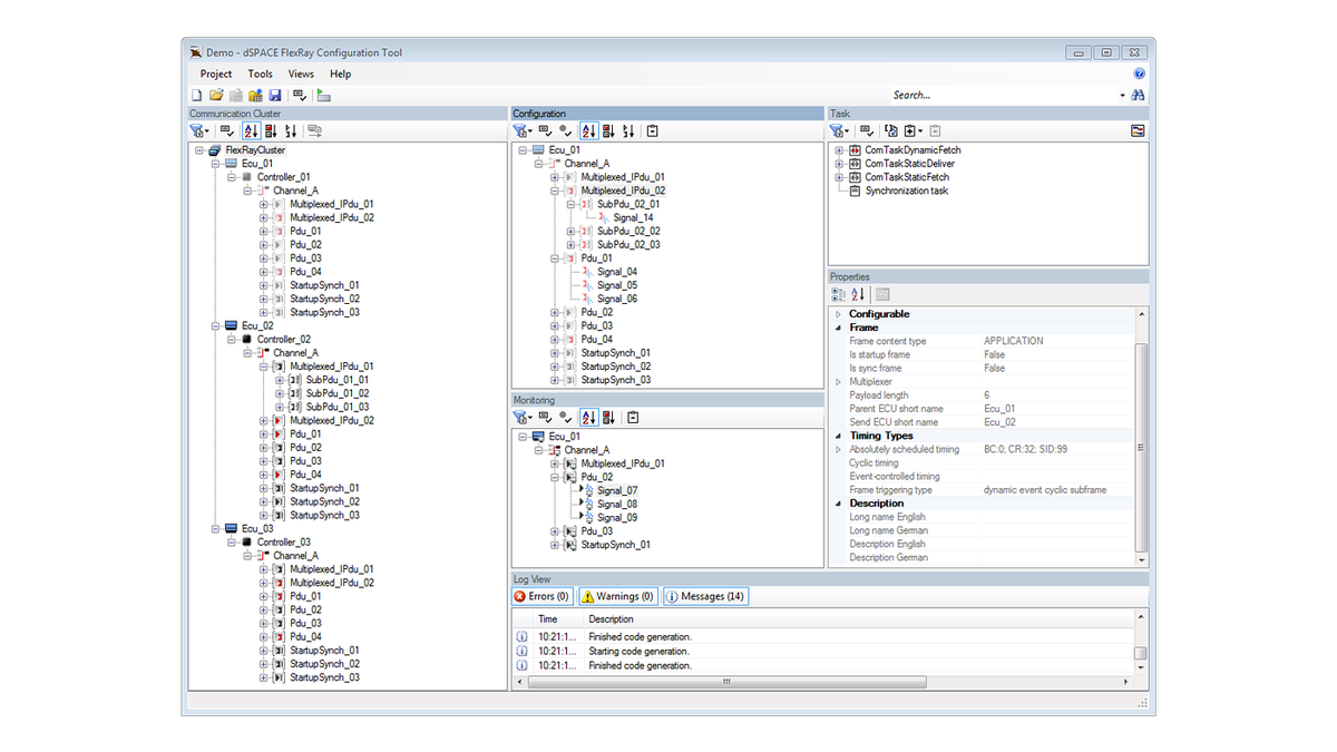
dSPACE FlexRay Configuration Tool
The dSPACE FlexRay Configuration Tool lets you configure a dSPACE system as a simulation node in a FlexRay network. It relies on the network and scheduling data available in a FIBEX or AUTOSAR XML representation. Numerous consistency checks are performed when the communication description is imported. Various views help manage the FlexRay configuration. The tool generates the communication code and controller configuration.
RTI FlexRay Configuration Blockset
Application-specific Simulink models can be created using the RTI FlexRay Configuration Blockset as a basis. The block attributes are filled with data generated by the dSPACE FlexRay Configuration Tool. The blockset contains additional blocks that can be used for task execution control, interrupt and error handling, status information, and controller reset. The RTI FlexRay Configuration Blockset supports the sending and receiving of protocol data units (PDUs), which are also used in AUTOSAR. Such units comprise several signals, which can be handled in the model by using only one Simulink block per PDU.
Working with dSPACE Tools
dSPACE hardware systems – from MicroAutoBox to SCALEXIO hardware – can be used for various fields of FlexRay applications. The systems are equipped with slots for modules containing a FlexRay communication controller. The application models are created in MATLAB®/Simulink® in combination with dSPACE‘s RTI blocksets. The models are executed on the hardware in real time. Model execution and bus access are synchronized. The results can be visualized in an experiment environment such as ControlDesk.
Selecting Signals, PDUs and Frames
The dSPACE FlexRay Configuration Tool is the bridge between the network or system level view and the node- or ECU-specific view. After a communication matrix or network description file is imported, the FlexRay network description and scheduling data are displayed in a clearly arranged hierarchical view. This is combined with additional display and sorting options. Furthermore, you can easily select all the PDUs (Protocol Data Units) you want to use in your simulation. If you want to set up a restbus simulation for a single ECU, just select the ECU and let the tool look up all the PDUs sent to it.
Automation Interface
The powerful automation interface allows users to perform all important configuration settings by means of automation, thus enabling highly efficient work. You can either export the configuration file from an existing project to reuse it in new projects or create the configuration file manually using the documentation. It is also possible to automatically generate configuration files using your customer-specific tooling. When the dSPACE FlexRay Configuration Tool is started (automatically), the configuration information is provided by means of parameters. In this way, the entire tooling can be automated.
Creating a Task Schedule
You can create a task schedule by selecting signals, frames for FIBEX 2.x and PDUs for FIBEX 3.x and AUTOSAR. The schedule includes communication routines for sending and receiving FlexRay frames, for both the static and the dynamic parts of the communication cycle. It also covers application tasks for your functional or restbus simulation models. The task schedule can be derived automatically according to a fixed scheme for positioning communication routines. Alternatively, you have full control to define it manually. When you do so, various checks are performed in the background to ensure the task schedule you define is consistent. The third and final category of tasks covers the synchronization task. This is executed at the end of each application cycle to align task execution to the global time on the FlexRay bus.
Code Generation
The configuration tool has been given all the information it needs to generate the actual communication code and the settings for initializing the FlexRay controller. The tool also calculates the required number of FlexRay controllers, taking into account the available communication buffers, and startup and synchronization behavior. The code generator is prepared to support NXP (Freescale) and Bosch E-Ray controller implementations for FlexRay1).
Creating the FlexRay Model
You can now take the results of the configuration tool, which acts as a kind of preprocessor tool, and continue with the usual model-based design flow. When a FlexRay model is created for the first time, blocks from the RTI FlexRay Configuration Blockset library are copied to the model and their parameter values are set automatically according to the configuration data that was generated previously. The resulting model frame represents a complete interface to the FlexRay network and a local task schedule. It can be supplemented by the actual functional or restbus simulation models and further blocks from the library, for example, for receiving status information and handling error situations.
Modifying the Model
Later on, you will most likely face modifications to the communication description file, representing new integration stages in the vehicle project. To preserve the modeling results already obtained, the RTI FlexRay Configuration Blockset comes with an update mechanism for handling changes in the configuration data, for example, introducing new signal and PDU blocks and discarding old ones. The resulting FlexRay application model is compiled for execution on a dSPACE hardware system. The driver and initialization code of the configuration tool is integrated during this build process. The generated code is downloaded to the dSPACE hardware and acts as a full-fledged node in the FlexRay network, sending and receiving FlexRay frames in real time.
Selected Failure Simulation Methods
- Failure and restart of a FlexRay controller
- Enable/disable transmission of a static frame
- Enable/disable transmission of a cyclic dynamic FlexRay frame
- Enable/disable all event-based dynamic FlexRay frames
- Enable/disable all cyclic FlexRay frames (a null frame or old value is sent)
- Alive counter manipulation via TRC file
- Change CRC algorithms at run time
- Send and receive invalid signals
- Simulate synchronization service breakdown
- Simulate time-triggered task execution breakdown with optional restart at correct synchronization
| Functionality | Description |
|---|---|
| Importing communication descriptions |
|
| Handling |
|
| Signal and frame selection |
|
| PDU handling |
|
| Frame handling |
|
| Task configuration |
|
| Support of AUTOSAR functions |
|
| Model generation |
|
| Simulation stage |
|
- MicroAutoBox II Compact, stand-alone prototyping unit with real-time hardware, I/O, and signal conditioning
- MicroAutoBox III Compact and robust in-vehicle prototyping system
Drive innovation forward. Always on the pulse of technology development.
Subscribe to our expert knowledge. Learn from our successful project examples. Keep up to date on simulation and validation. Subscribe to/manage dSPACE direct and aerospace & defense now.