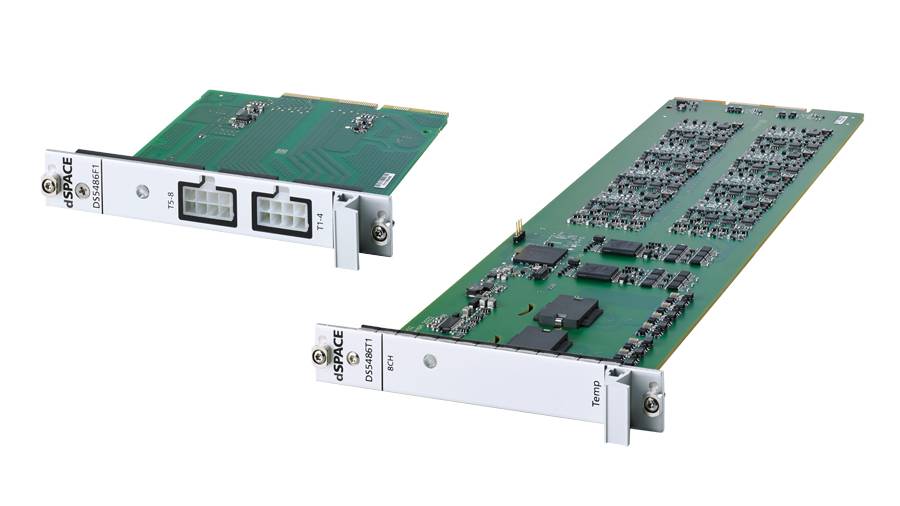
DS5486 Temperature Simulation Board
High-end board for emulating resistor-based temperature sensors at cell level
The high-precision DS5486 Temperature Simulation Board is an eight-channel SCALEXIO board for hardware-in-the-loop (HIL) testing of cutting-edge battery management systems (BMS) on the voltage level. It enables the emulation of temperature sensors at cell level for system voltages of up to 1,500 V and comes with integrated electrical failure simulation. The board can be used for a wide range of BMS use cases across different industries – from battery electric vehicles to stationary storage systems.

High-voltage (HV) batteries used in electric vehicles and other energy storage applications must be operated within a certain temperature range. To prevent a battery from overheating, it is important to measure and control its temperature. This extends the battery life and increases its safety.
A battery is therefore equipped with several sensors which measure local temperatures. The DS5486 simulates these temperature sensors with high precision.
Depending on the simulated battery type and test focus, several boards can be combined in one or more 19" slot units within a SCALEXIO Battery HIL system. The boards are controlled by a dynamic thermal battery simulation model running on the HIL system.
The boards emulate the resistances of up to eight typical temperature sensors within the range of 20 Ω to 1 MΩ. This relatively wide range means that all usual negative and positive temperature coefficient (NTC and PTC) sensors can be emulated for a wide temperature range. Sensor emulation is performed at a resolution of 19 bits with high dynamic accuracy.
Thanks to the fast and low-latency IOCNET connection to the SCALEXIO real-time system, updating the resistor values of all boards takes less than 200 µs.
Technical Details
Parameter |
Specification1) |
|---|---|
|
Hardware structure |
|
|
Sensor resistance range |
|
|
Sensor programming resolution |
|
|
Precision (for positive sensor voltages and depending on the adjusted resistance value) |
|
|
Maximum sensor voltage |
|
|
Maximum sensor power dissipation |
|
| Isolation |
|
| Connection |
|
| Maximum update rate for all sensors |
|
| Failure simulation |
|
1) Preliminary data. For technical specifications, please contact dSPACE.

