| Parameter |
Specification 1 |
Specification 2 |
Specification 3 |
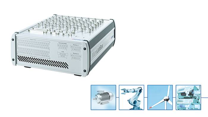
| MicroLabBox Variants |
Front Panel Variant |
Top Panel Variant with BNC Connectors |
Top Panel Variant with Spring-Cage Terminal Blocks |
| Processor |
- Real-time processor
- NXP (Freescale) QorlQ P5020, dual-core, 2 GHz 32 KB L1 data cache per core, 32 KB L1 instruction cache per core, 512 KB L2 cache per core, 2 MB L3 cache total
- Host communication
- NXP (Freescale) QorlQ P1011 800 MHz for communication with host PC
- Memory
- 1 GB DRAM 128 MB flash memory
- Boot time
- Autonomous booting of applications from flash (depending on application size), ~5 s for a 5 MB application
|
| Interfaces |
- Host interface
- Integrated Gigabit Ethernet host interface
- Ethernet real- time I/O interface
- Integrated low-latency Gigabit Ethernet I/O interface
- USB interface
- USB 2.0 interface for data logging ("flight recorder") and booting applications via USB mass storage device (max. 32 GB supported)
- CAN interface
- 2 CAN channels (partial networking supported)
- Serial interface
- 2 x UART (RS232/422/485) interface
- LVDS interface
- 1 x LVDS interface to connect with the Programmable Generic Interface PGI1
- Programmable FPGA1)
- Xilinx® Kintex®-7 XC7K325T FPGA
|
| Analog input |
- Resolution and type
- 8 14-bit channels, 10 Msps, differential; functionality: free running mode
- 24 16-bit channels, 1 Msps, differential; functionality: single conversion and burst conversion mode with different trigger and interrupt options
- Input voltage range
|
- Resolution and type
- 8 14-bit channels, 10 Msps, differential; functionality: free running mode
- 24 16-bit channels, 1 Msps, differential; functionality: single conversion and burst conversion mode with different trigger and interrupt options
- Input voltage range
|
- Resolution and type
- 8 14-bit channels, 10 Msps, differential; functionality: free running mode
- 24 16-bit channels, 1 Msps, differential; functionality: single conversion and burst conversion mode with different trigger and interrupt options
- Input voltage range
|
| Analog output |
- Resolution and type
- 16 16-bit channels, 1 Msps, settling time: 1 µs
- Output voltage range
- Output current
|
- Resolution and type
- 16 16-bit channels, 1 Msps, settling time: 1 µs
- Output voltage range
- Output current
|
- Resolution and type
- 16 16-bit channels, 1 Msps, settling time: 1 µs
- Output voltage range
- Output current
|
| Digital I/O |
- 48 bidirectional channels, 2.5/3.3/5 V (single-ended); functionality: bit I/O, PWM generation and measurement (10 ns resolution), pulse generation and measurement (10 ns resolution), 4 x SPI Master 12 bidirectional channels (RS422/485 type) to connect sensors with differential interfaces
|
- 48 bidirectional channels, 2.5/3.3/5 V (single-ended); functionality: bit I/O, PWM generation and measurement (10 ns resolution), pulse generation and measurement (10 ns resolution), 4 x SPI Master 12 bidirectional channels (RS422/485 type) to connect sensors with differential interfaces
|
- 48 bidirectional channels, 2.5/3.3/5 V (single-ended); functionality: bit I/O, PWM generation and measurement (10 ns resolution), pulse generation and measurement (10 ns resolution), 4 x SPI Master 12 bidirectional channels (RS422/485 type) to connect sensors with differential interfaces
|
| Electric motor control I/O functionality |
- Separate interfaces
- Functionality on digital I/O channels
- 6 x Encoder sensor input
2 x Hall sensor input
2 x EnDat interface
2 x SSI interface
Synchronous multi-channel PWM
Block commutational PWM
- Sensor supply
- 1 x 12 V, max. 3 W/250 mA (fixed) 1 x 2 ... 20 V, max. 1 W/200 mA (variable)
- Feedback elements
- Programmable buzzer
Programmable status LEDs
- Theft protection
- Cooling
- Active cooling (temperature-controlled fan)
- Physical connections
- 4 x Sub-D 50 I/O connectors
4 x Sub-D 9 I/O connectors
3 x RJ45 for Ethernet (host and I/O)
USB Type A (for data logging)
2 x 2 banana connectors for sensor supply Power supply
|
- Separate interfaces
- Functionality on digital I/O channels
- 6 x Encoder sensor input
2 x Hall sensor input
2 x EnDat interface
2 x SSI interface
Synchronous multi-channel PWM
Block commutational PWM
- Sensor supply
- 1 x 12 V, max. 3 W/250 mA (fixed) 1 x 2 ... 20 V, max. 1 W/200 mA (variable)
- Feedback elements
- Programmable buzzer
Programmable status LEDs
- Theft protection
- Cooling
- Active cooling (temperature-controlled fan)
- Physical connections
- 2 x Sub-D 50 I/O connectors 48 x BNC I/O connectors
4 x Sub-D 9 I/O connectors
3 x RJ45 for Ethernet (host and I/O)
USB Type A (for data logging)
2 x 2 banana connectors for sensor supply Power supply
|
- Separate interfaces
- Functionality on digital I/O channels
- 6 x Encoder sensor input
2 x Hall sensor input
2 x EnDat interface
2 x SSI interface
Synchronous multi-channel PWM
Block commutational PWM
- Sensor supply
- 1 x 12 V, max. 3 W/250 mA (fixed) 1 x 2 ... 20 V, max. 1 W/200 mA (variable)
- Feedback elements
- Programmable buzzer
Programmable status LEDs
- Theft protection
- Cooling
- Active cooling (temperature-controlled fan)
- Physical connections
- 2 x Sub-D 9 I/O connectors 27 x spring-cage terminal block connectors with 8 pins each 3 x RJ45 for Ethernet (host and I/O)
USB Type A (for data logging)
2 x 2 banana connectors for sensor supply Power supply
|