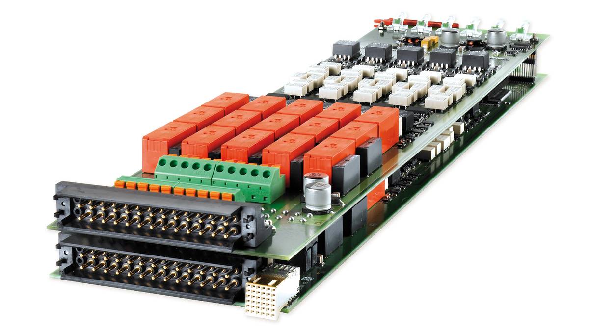
DS2601 Signal Measurement Board
HighFlex board for measuring ECU output signals
The DS2601 is used in SCALEXIO hardware-in-the-loop simulators. It provides current and voltage measurement during HIL tests of ECUs. The DS2601 can be equipped with onboard loads or external loads via a second connector.
- Channel bundling to increase current carrying capacity
- On-board failure routing unit
- Galvanically isolated channels
Application Area
The DS2601 Signal Measurement Board measures ECU output signals and passes the measurement values to the real-time processor. Signal measurement can be time-triggered or event-triggered, and the execution of signal measurement can be voltage- or current-triggered.
Key Benefits
The DS2601 offers 10 versatile, software-configurable channels that can be used as analog or digital input for measuring voltage and current. The channels can be connected in parallel to increase the current-carrying capacity up to 80 A (RMS).
The board also includes an onboard failure routing unit.
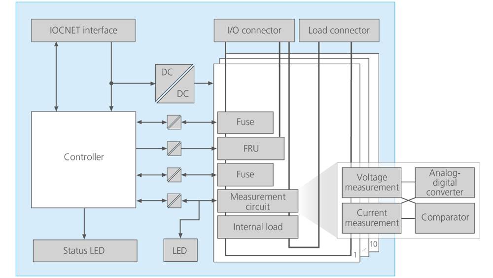
I/O Functionality
The DS2601's input channels can connect analog as well as digital measurement units (analog-digital converters or comparators, respectively) to measure the current and voltage. For example, the measurement units can be combined to trigger analog current measurement if a specified voltage is exceeded. The channels are defined and configured in the ConfigurationDesk software.
The 10 channels on the DS2601 can be connected in parallel. This channel bundling increases the current-carrying capacity up to 80 A (RMS). ConfigurationDesk displays the bundled channels as one single I/O function. The DS2601 supports the use of loads for the ECU. You can either plug substitute loads onto the board itself or connect real loads via a cable harness to the externally accessible load connector.
| Parameter | Specification |
|---|---|
| General |
|
| Electrical capacity |
|
| Signal measurement (Flexible In 1) |
|
| Fault simulation |
|
| Electronic fuses |
|
| Internal communication interface |
|
| Physical size |
|
| Voltage supply |
|
| Typical power consumption |
|
-
- View online
- Download
- Fault Simulation dSPACE SCALEXIO는 고장 시뮬레이션을 위한 유연한 라이선스 개념을 제공합니다.
- ConfigurationDesk Configuration and implementation software for dSPACE real-time hardware
혁신을 추진하세요. 항상 기술 개발의 동향을 주시해야 합니다.
저희 전문 지식 서비스에 가입하세요. dSPACE의 성공적인 프로젝트 사례를 확인해 보세요. 시뮬레이션 및 검증에 대한 최신 정보를 받아보세요. 지금 바로 dSPACE 다이렉트(뉴스레터)를 구독하세요.