Software-in-the-loop (SIL) testing has become an integral part of software development in the automotive industry. At the same time, the short abbreviation SIL covers a very wide range of topics. This blog article describes what SIL simulation means and which requirements and challenges it entails.
First of all, SIL testing means nothing more than that software – no matter in which state – is used in a simulated environment to put it through its paces, to check the bits and bytes. And that is exactly where the subtleties begin: Testing a piece of C code or a single software function requires a different test environment and different test scenarios than a complete ECU network. It is also necessary to distinguish between testing the software with a pure stimulation of the interfaces (open-loop) and integration with, for example, a closed-loop plant model (closed-loop).
General Structure of a SIL Environment
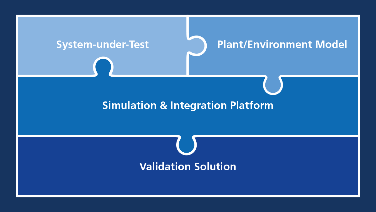
Regardless of the operational scenario, a SIL test environment is comprised of four elements:
- The software to be tested, i.e., the system under test (SUT)
- The simulation models for the environment simulation
- The simulation and integration platform, i.e., the system on which the system under test and the simulation models are put together and implemented
- The validation environment, i.e., for control, configuration and evaluation
The scope and requirements of these four elements are dependent on the software to be tested. The following sections illustrate this using the example of a newly developed software function for an advanced driver assistance system that is to be tested in the overall network. However, two fundamental questions need to be answered before testing can start: How do I get my software into the virtual world and which environment models do I need as a counterpart for this?
System Under Test – From Software to Virtual ECU
The system under test (SUT) is the focus of every test because it is precisely the software that will later have to prove itself on an ECU in real-world use. The SIL tests run completely without ECU hardware, which leads to many advantages, e.g., lower costs, easy scalability in the cloud, etc. But can realistic operating conditions even be represented without hardware?
Unlike soft ECUs, which work with simplified Simulink®//Stateflow® models, SIL testing uses virtual ECUs (V-ECUs) for this purpose. In general, a virtual ECU can be any type of ECU software – from a simple function to the complete hardware-independent software of an ECU. The big difference from simple models is that V-ECUs are based on real production code. V-ECUs can also have different levels of abstraction, depending on where they are used. In the industry, the classification into five levels has become established for characterization purposes, which are briefly outlined below:
Five Established Abstraction Levels for V-ECUs
Level 0
In the simplest case, a model is available, for example, in MATLAB/Simulink or as a Functional Mock-up Unit (FMU). This means that only tests of the control algorithm of the ECU are possible, since, for example, the basic software or the production code of the control application are missing.
Level 1
In this case, the V-ECU contains the original production code from individual applications up to the entire application layer of a real ECU. Further components, such as functions of the basic software (BSW), must be provided by the simulation environment or simplified BSW for the simulation must be integrated into the V-ECU.
Level 1 V-ECUs operate at signal level and enable, for example, the testing of functions that are distributed across various components.
Level 2
By extending the V-ECU with parts of the basic software, which is created for the purpose of simulation, tests on the bus and network level are made possible. The test is still aimed at the function of the application software but is extended to include functions such as bus monitoring, diagnostic interfaces, or restbus models.
Level 3
A Level 3 V ECU also contains production code of the basic software. It can be used, for example, to test the software integration of an ECU or also for the integration test of several ECUs.
Level 4
If the production code was compiled for the ECU hardware or contains hardware dependencies, the integration of an instruction set simulation is necessary.
How do I create a V-ECU?
Depending on the project context, SUTs or V-ECUs already exist and only have to be executed on or coupled to the simulation and integration platform, for example, as an FMU, ROS algorithm, or even as a V-ECU artifact in dSPACE format. Then there is no need to create your own V-ECU. However, if only the code is available, it must be linked to the simulator interfaces and possibly supplemented with functions for the simulation. dSPACE offers options for doing just that; this is V-ECU creation.
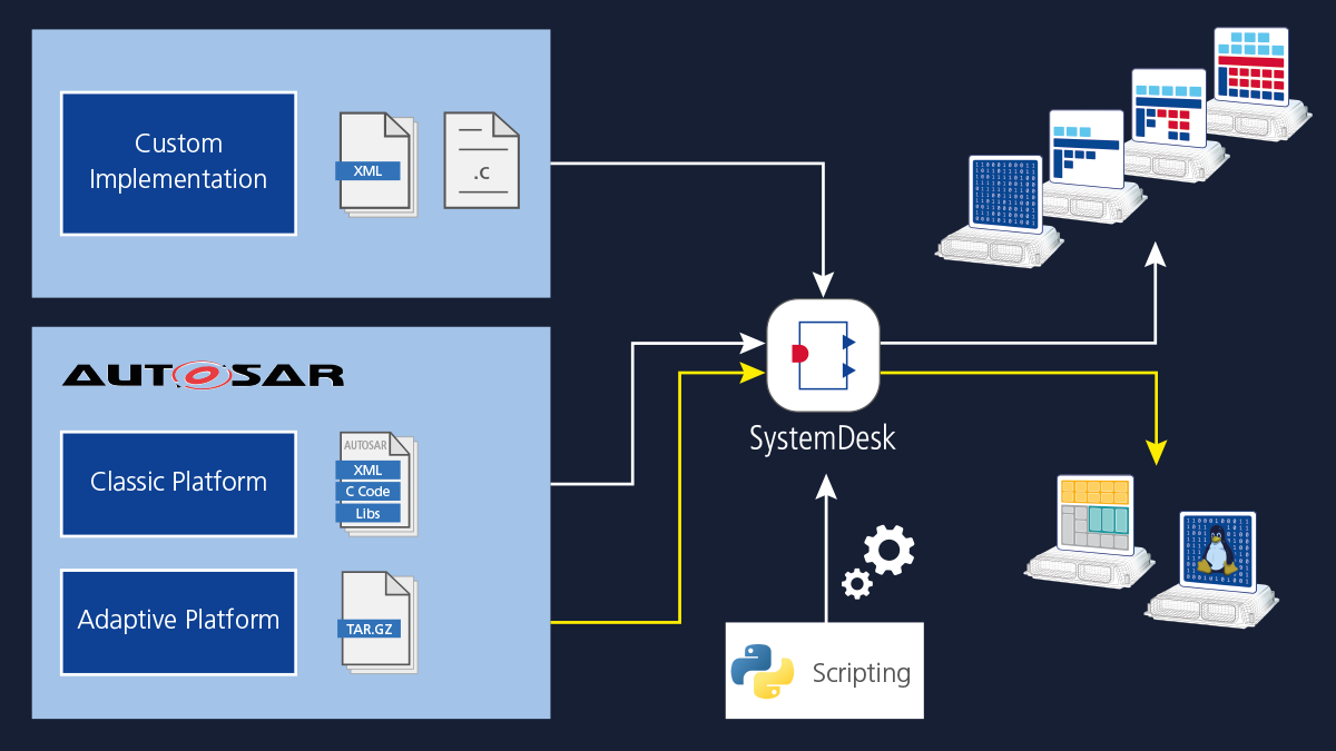
There are various ways to create a V-ECU in the dSPACE tool chain, depending on the application area, project requirements, and on whether the development is based on AUTOSAR. Function and software developers who just work with individual components can create a V-ECU directly with Simulink or TargetLink. The result is a simple V-ECU (level 1) which is made up of only a selected part of the application layer of the ECU software. It enables basic function tests. Similarly, with the V-ECU SDK, C or C++ functions can be connected directly from an IDE to interfaces of the VEOS simulator and then debugged during the simulation, also in the IDE.
For our example, in which the software is to be tested in the overall network, this is not sufficient. We need a V-ECU that contains as much as possible of the real ECU. For this, software components, functions, basic software, and non-AUTOSAR code from different sources must be combined. This is all done centrally with the SystemDesk software. The overall V-ECU generated in this way contains the run-time environment (RTE) and parts of the basic software (levels 2 to 3) in addition to the application layer. The run-time environment and software parts are connected to VEOS interfaces by SystemDesk. With such a V-ECU, extensive tests including bus monitoring and diagnostic interfaces, for example, are possible.
Generating V-ECUs from production code for existing ECUs can be challenging when implementing SIL testing. We have several years of experience from many customer projects with all types of V-ECUs. To successfully implement SIL, we offer support on how to best approach V-ECU generation in specific cases.
Simulation Models for a Closed Loop
Simulation models represent the necessary counterpart to the SUT. Thus, realistic input variables are provided, and corresponding output variables are sensibly processed by the SUT to enable an entire virtual test drive. This results in a wide range of requirements for the simulation models – from the simulation of realistic vehicle dynamics and different powertrain variants to complete traffic simulations with numerous participants and realistic 3-D environments with different weather phenomena and corresponding physics-based sensor models. Depending on the function to be tested, different levels of abstraction are also required. Examples of suitable simulation models with a wide range of details for vehicle and powertrain variants are provided by the dSPACE Automotive Simulation Models (ASM). With dSPACE AURELION, detailed 3-D environment and sensor models are available. This allows all automotive domains, especially ADAS/AD applications and e-mobility, to be addressed and to be developed and validated in a closed loop.
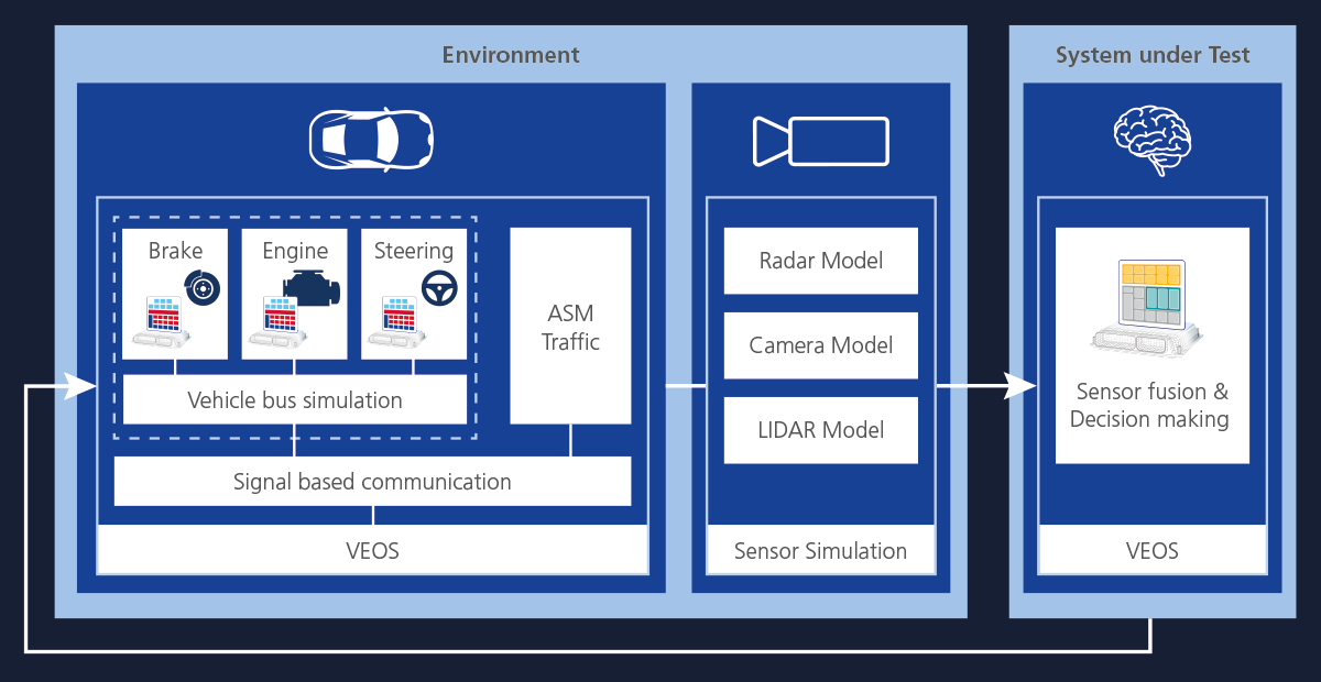
A typical example of an interaction of the SUT with the plant model is shown in Figure 3. In addition to the vehicle status, the SUT expects the data from the environment sensors and plays back the result of the trajectory planning to the actuator system. Thus, in order to be able to test the SUT under realistic conditions, several ECUs are involved, which in turn have their own demands on the vehicle and environmental models. Sensor simulation plays a particularly important role in this context and can be flexibly configured from simple object lists to realistic data such as lidar point clouds.
Now that the SUT is available as a V-ECU and the models have been selected, one key question remains: How can the various components be connected with each other for complete simulation?
Simulation and Integration Platform
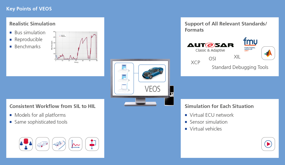
VEOS is used as a central platform for the simulation and integration of the various simulation components. There, the V-ECUs and simulation models as well as everything else needed for simulation can be brought together. VEOS is not limited to dSPACE artifacts and tools but supports all relevant standards. If integration via standards is not possible, co-simulation can be used. This allows the integration of versatile components ranging from third-party models to other middleware (ROS etc.), POSIX-based ECUs, and level 4 V-ECUs (instruction set simulation).
As a central platform, VEOS is also responsible for the simulation itself. VEOS handles time synchronization and communication between the various simulation components. The time synchronization makes the simulation independent from real-time conditions. Therefore, the simulation not only does not require any hardware, but in many cases also runs faster than on the HIL. It is deterministic and therefore reproducible – if all connected artifacts allow this. At the same time, the time synchronization enables an exact representation of the communication. VEOS enables both signal-based communication between the simulation participants and the exchange of bus messages. VEOS simulates the real buses by also taking into account the timing behavior of the bus communication. Similar to the HIL, bus communication in VEOS can be accessed for monitoring bus messages and fault injection.
Despite its central role and large scope of features, VEOS is a lightweight platform that can be scaled from the desktop PC to the cloud. Therefore, tests are possible from an individual ECU to a virtual vehicle.
Once a sufficient level of software maturity has been demonstrated in SIL testing, the switch to the HIL simulator is effortless, as components and experiments from the SIL can be reused.
Automatic Validation
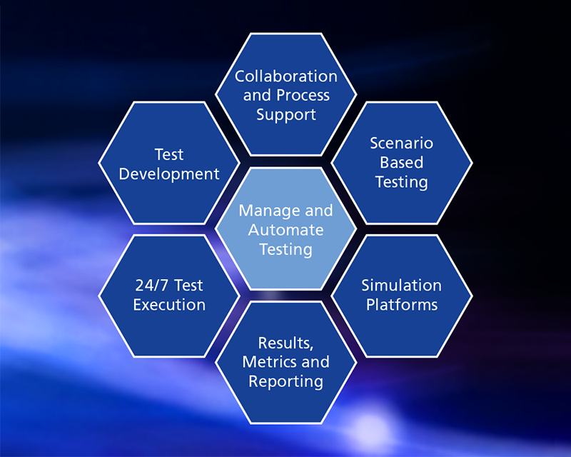
To keep track of extensive test campaigns, the only thing missing is a central validation environment. High demands are placed on these: Firstly, the simulation has to be configured, controlled, and later automated. The tests should be planned and executed centrally, taking into account different test methodologies, for example, requirements-based or scenario-based testing. This results in a decisive advantage: Tests can be carried out 24/7 and allow collaboration across locations. At the same time, direct traceability of requirements, test cases, and test reports is possible, as recommended by ISO 26262.
With the Test Solution Package (AutomationDesk in conjunction with SYNECT) and SIMPHERA, dSPACE offers two solutions that address two different application focuses and both fit seamlessly into the tool chain.
Both solutions offer support in the three significant phases which are important for successful testing: The test creation, the implementation of the created test, and the management of all artifacts including the results that are relevant for the tests.
For test creation, it is important for the user to have a simple yet powerful interface for configuring test cases. This is possible in all domains using AutomationDesk for typical requirements-based tests. For special ADAS/AD-oriented tests such as scenario-based testing, SIMPHERA offers an intuitive interface for configuring such tests. The tests created in AutomationDesk are then typically managed in SYNECT, from where they can also be brought to execution on globally distributed HIL platforms, for example. The results are stored in a central database and are thus centrally available, which promotes collaboration. In addition, the results are also linked to the requirements covered by the test with the help of ALM tools (tools in which requirements for the software are described and traced). As a cloud-native solution, SIMPHERA offers advantages in the scaled execution of scenario-based tests, which lead to an enormous amount of specific test cases due to a large set of parameters and large parameter ranges. Massively parallel, scaled execution in the cloud greatly reduces the time required to generate the necessary test results. Here, too, the results are stored centrally in a database, where they are available for further analysis.
About the author:

Barbara Kempkes
Product Manager, Automated Driving & Software Solutions, dSPACE GmbH