Real-Time Interface (RTI)
Implementation software for running models on dSPACE hardware
RTI lets you concentrate fully on the actual design process and carry out fast design iterations. It extends the C code generator Simulink Coder™ (formerly Real-Time Workshop®) for the seamless, automatic implementation of your Simulink and Stateflow models on the real-time hardware.
- Implementation of MATLAB®/Simulink®/ Stateflow® models on dSPACE hardware
- Automatic code generation
- Graphical I/O configuration via comprehensive Simulink block libraries

Application Areas
No matter whether you are performing rapid control prototyping or hardware-in-the-loop simulation: Real-Time Interface (RTI) is the link between dSPACE hardware and the development software MATLAB/Simulink/Stateflow from MathWorks®.
Working with RTI
To connect your model to a dSPACE I/O board, just drag & drop the I/O module from the RTI block library and then connect it to the Simulink blocks. All settings, such as parameterization, are available by clicking the appropriate blocks. Simulink Coder™ (formerly Real-Time Workshop®) generates the model code while RTI provides blocks that implement the I/O capabilities of dSPACE systems in your Simulink models, thus preparing the model for the real-time application. Your real-time model is compiled, downloaded, and started automatically on your real-time hardware, without you having to write a single line of code. RTI guides you during the configuration. RTI provides consistency checks, so potential errors can be identified and corrected before or during the build process.
Comprehensive Functionalities
RTI handles any kind of continuous-time, discrete-time, and multirate system. Depending on the I/O hardware, different channels of the same I/O board can be used with different sample rates, and even in different subsystems. RTI supports asynchronous events and lets you set task priorities and task overrun strategies for executing the interrupt-driven subsystems. It also supports time-triggered tasks and timetables, which allow you to implement tasks and groups of tasks with variable or predefined delay times in relation to an associated trigger event. This makes task handling in your model very flexible. In addition, RTI offers checks which help avoid double or improper use of channels.
Key Benefits
RTI lets you concentrate fully on the actual design process and carry out fast design iterations. It extends the C code generator Simulink Coder™ (formerly Real-Time Workshop®) for the seamless, automatic implementation of your Simulink and Stateflow models on the real-time hardware. The implementation time is greatly reduced. RTI guides you through the hardware configuration and provides automatic consistency checks to avoid parameterization errors. For maximum flexibility, each RTI version supports several different MATLAB releases (see www.dspace.com/go/Compatibility). Models from most previous MATLAB and RTI releases are migrated automatically when newer versions of RTI are used.
Model Design
In this example, the closed control loop of the positioning system for a hard disk drive is shown in the block diagram. Both the controller and the model of the controlled system are designed in the MATLAB/Simulink development environment.
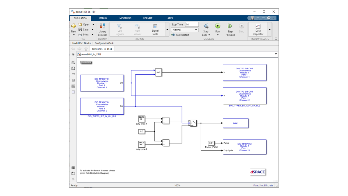
Graphical I/O Configuration
When you have finished testing your model in Simulink, it has to be prepared for implementation on the real-time hardware. The plant model is replaced by I/O blocks that form the interfaces to the real controlled system. To add an I/O model, simply drag a block from the RTI I/O library to the model and connect the block with the I/O of the controller.
Parameter Specification
I/O parameters are specified by double-clicking an I/O block and entering the data in graphical user interfaces. In this example, the input signals are the feedback value and the reference signal. The reference signal now comes from an external signal generator and is read in by an ADC block. The output signal from the controller is the control signal u_M, which is output by the hardware via a DAC block.
Implementation on dSPACE Hardware
Automatic implementation of the Simulink model on dSPACE hardware is the key to rapid design iterations. With RTI you will not see a single line of code during this process. A single click on Build starts the implementation, including code generation, compiling, and downloading. You can select an integration algorithm and a step size in the Solver page of the Configuration Parameters dialog. Build procedures can also be automated with the help of scripts. This is especially useful for large models.
Interaction with Experiment Software
When your application is running on the real-time hardware, the whole dSPACE experiment software is at your disposal. RTI ensures that you have control over each individual variable immediately after the implementation process.
ControlDesk provides an instrument panel that enables you to change parameters and monitor signals – without regenerating the code. ControlDesk also displays the time histories of any variable used by your application.
Supporting dSPACE Hardware
No matter whether you are using dSPACE systems with a DS1104 R&D Controller Board, MicroAutoBox II, or MicroLabBox: RTI allows for the convenient model and I/O configuration of your dSPACE system.
|
Blockset |
Description |
Further Information (See relevant product information) |
|
Real-Time Interface for Multiprocessor Systems |
|
|
|
RTI Bypass Blockset |
|
|
|
CAN Blocksets |
|
|
|
RTI LIN MultiMessage Blockset |
|
|
|
dSPACE FlexRay Configuration Package |
|
|
|
FPGA Programming Blockset |
|
|
|
Ethernet Blocksets |
|
|
|
RTI Electric Motor Control Blockset |
|
|
|
RTI DS1552 I/O Extension Blockset |
|
|
|
RTI RapidPro Control Unit Blockset |
|
|
|
RTI USB Flight Recorder Blockset |
|
– |
|
RTI Watchdog Blockset |
|
|
|
RTI Synchronized Time Base Manager Blockset |
|
– |
| Functionality | Description |
|---|---|
| I/O configuration |
|
| Generating real-time code |
|
| Automatic task definition |
|
| Invoking the compiler |
|
| Loading and starting the application |
|
Drive innovation forward. Always on the pulse of technology development.
Subscribe to our expert knowledge. Learn from our successful project examples. Keep up to date on simulation and validation. Subscribe to/manage dSPACE direct and aerospace & defense now.