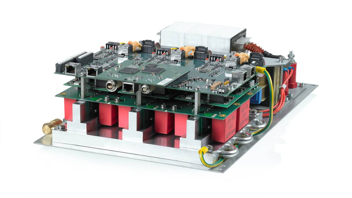
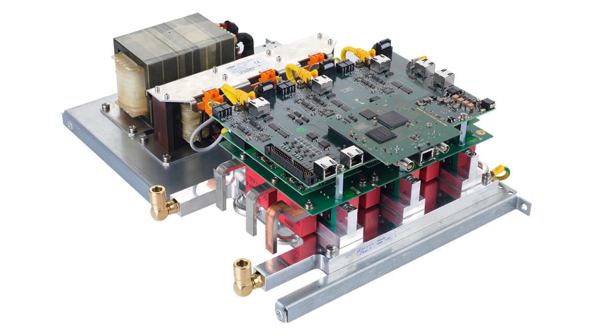
DS5386 High-Voltage Electronic Load Module
Electronic load for power HIL simulation up to 1,250 V
The DS5386 High-Voltage Electronic Load Module from dSPACE makes it possible to emulate electric motors, batteries, and power grids for hardware-in-the-loop (HIL) simulation. Consequently, this allows for tests of power electronics control units with voltages of up to 1,250 V and several megawatts of power.
- Compact and modular hardware for different applications and application topologies
- Modules can be connected in parallel for increased power output
- Based on silicon carbide (SiC) technology
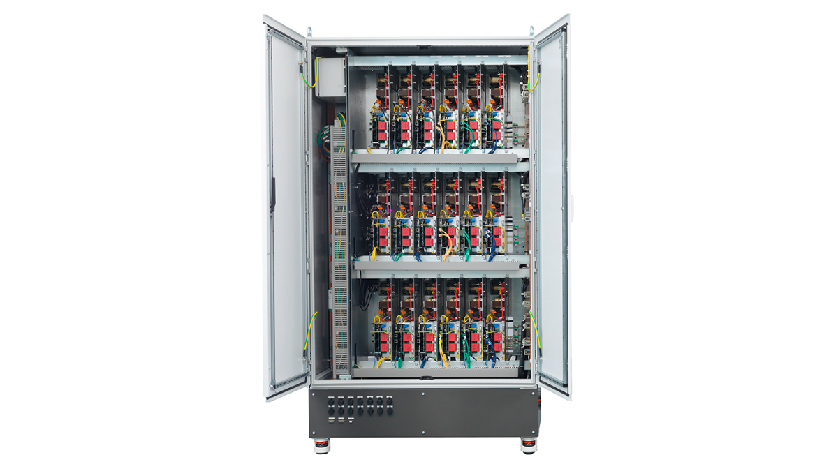

One of the most common use cases in this area is inverter testing for automotive traction motors, industrial drives, and zero-emission aircraft. However, the highly flexible electronic load can also emulate any AC and DC source, which is why it can operate as any conceivable electrical network, on land, in the air, and at sea, and also as a battery emulator. The DS5386 High-Voltage Electronic Load Module can be integrated into an emulator cabinet from dSPACE to form a power HIL test system. Tailor-made for HIL simulation at the power level, these systems bridge the gap between signal HIL tests and tests on dynamometers or in prototype vehicles.
Key Benefits
- Smooth, quasi-continuous current representation thanks to the cutting-edge multi-level hardware architecture and the patented observer-based model predictive current control (MPC)
- Low-latency model interface that enables the current-based emulation of electrical frequencies of up to several kHz
- Expandability using identical modules for supply and load emulation
- Compact design with high energy density for an assembly with minimum space requirements
- Water-cooled power electronics for user-friendly environmental conditions
- Efficient operation due to a circular energy flow without energy recovery to the mains (less than 15% of emulation power required by power supply due to energy recovery)
Thanks to the modular approach of the dSPACE power HIL test systems, they can be easily adapted to a wide range of applications and individual power ranges. For this purpose, the systems are configured with the required number of DS5386 High-Voltage Electronic Load Modules.
The configurations indicated here are the minimum configurations that can be installed in one emulator cabinet. It is possible to connect several modules or even several cabinets in parallel to achieve higher power outputs. Thus, any system in the voltage range between 0 and 1,000 V and in the power range from a few kW up to several MW can be set up.
| Application | Configuration |
|---|---|
| Solar Inverter Testing |
|
| Wind Inverter Testing |
|
| Back-to-Back Industrial Drive Testing |
|
| Motor Inverter Testing (for Three-Phase Separately Excited Synchronous Motors, SESM) |
|
| Motor Inverter Testing (for Six-Phase Permanent Magnet Synchronous Motors, PMSM) |
|
| DC/DC Converter Testing |
|
| Onboard Charger Testing |
|
| Parameter | Specifications |
|---|---|
| Voltage |
|
| Current (AC) |
|
| Current (DC) |
|
| Power |
|
| Modularity |
|
| Power supply |
|
| Hardware topology |
|
| Power electronics technology |
|
| Protection |
|
| Cooling |
|
| Resulting switching frequency |
|
| Controller update rate |
|
| HIL interface |
|
| HIL interface update rate |
|
Drive innovation forward. Always on the pulse of technology development.
Subscribe to our expert knowledge. Learn from our successful project examples. Keep up to date on simulation and validation. Subscribe to/manage dSPACE direct and aerospace & defense now.