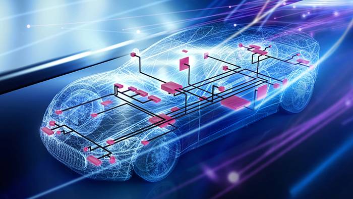
Bus and network systems are complex domains involving a variety of protocols, architectures, and algorithms used to develop, test, and validate bus and network communication. Explore everything from foundational concepts to the latest advancements in bus and network technologies — from CAN and LIN to Automotive Ethernet with SOME/IP and DDS.
Why In-Vehicle Communication Matters
Today’s vehicles are complex systems of interconnected ECUs that manage everything from basic functions to advanced driver assistance and autonomous driving. These systems rely on robust in-vehicle communication networks to exchange data reliably, securely, and in real time. Over the years, bus protocols have evolved from simple, low-bandwidth solutions like LIN or CAN to high-performance technologies like Automotive Ethernet. This shift has been driven by growing demands for bandwidth, security, and efficiency - especially as vehicles become more software-defined and feature-rich.
Architectures have also changed: traditional domain-based designs are giving way to zonal architectures, which reduce wiring complexity and support modular vehicle platforms. These zonal architectures represent a major shift in how vehicles are designed and built. Instead of distributing ECUs throughout the vehicle or grouping them by function, zonal designs divide the vehicle into physical zones. Each zone is managed by a zonal controller, which communicates with central high-performance compute units (HPCs) that handle most of the vehicle’s software logic. Despite this consolidation within zonal architectures, communication needs vary by vehicle type - electric vehicles, commercial fleets, and off-highway machines each bring unique requirements. Understanding these protocols and architectures is essential for building reliable, scalable automotive systems.
CAN - The Backbone of Embedded Automotive Communication
The Controller Area Network (CAN) is one of the most established and widely used communication protocols in the automotive industry. Originally developed by Bosch in the 1980s, CAN was designed to enable robust, real-time communication between electronic control units (ECUs) without the need for a central host computer. Since then, it has become a global standard not only in passenger vehicles but also in off-highway machinery, agricultural equipment, aerospace systems, and industrial automation. It enables the exchange of measurement and control signals and provides high fault tolerance through built-in error detection and handling mechanisms.
The physical implementation of CAN requires a CAN Controller, a transceiver as well as a microprocessor. CAN is a message-oriented communication protocol using a broadcast system where messages are identified by so called “message identifiers”. Receivers decide whether to accept a message based on its identifier. The identifiers also determine message priority during bus arbitration using the CSMA/CR (carrier sense multiple access with collision resolution) method. Any ECU can start transmission if the bus is idle after an intermission of three-bit times. If a collision occurs, the message with a higher priority “wins”. The priority is determined by the message identifier (a lower number means a higher priority). The highest priority message then continues without delay, while the others back off and retry once the bus is free.
Protocol Layers and Variants
Classic CAN is defined by the ISO 11898 standard. There are three important CAN standards that define the bus:
- ISO 11898-1 defines the data link layer according to the original CAN 2.0A and CAN 2.0B specification. To meet newer bandwidth demands, variants like CAN FD (Flexible Data Rate) or CAN XL (extended data-field length) extend this standard with increased payload sizes and significantly increased data rates.
- ISO 11898-2 (high-speed) and ISO 11898-3 (low-speed/fault-tolerant) cover the physical layer of the OSI model. They support data rates of up to 1 Mbit/s (high speed) and 125 kbit/s (low speed).
- ISO 11898-4 represents an extension to the data link layer for deterministic communication of safety-critical messages called “Time Triggered CAN”.
In contrast to other buses, the original specification only covers the lower two levels of the ISO/OSI model. Therefore, while CAN itself does not define an application layer, several higher-layer protocols have emerged to fill this gap, including SAE J1939 for commercial vehicles, CANopen for industrial automation and ISOBUS for agriculture applications. The ISO 11898 standards do not specify any security mechanisms. Protective measures such as authentication, integrity and confidentiality are implemented in higher protocol layers.
CAN Frame Format
CAN messages are transmitted in structured frames containing header, payload and trailer elements. The two main types are:
- Base frame format: 11-bit identifier
- Extended frame format: 29-bit identifier
Standard frames (11-bit identifiers) and extended frames (29-bit identifiers) can coexist on the same CAN network. In addition to data frames, CAN also supports error frames and overload frames, which help manage communication integrity and timing.
Each message starts with a start bit followed by the identifier. As a message can have a variable payload length of up to eight bytes for classic CAN, the exact length is specified within the “control bits”. The payload is then followed up by a “cyclic redundancy check” for error recognition as well as a variable number of stuff bits for synchronisation purposes. Lastly all ECUs connected to the bus will either give a positive confirmation within the acknowledge (ACK) and end of frame (EOF) fields or an error frame (EF) will lead all recipients to ignore the received data. This ensures data consistency within the network.
Network Topology
CAN networks typically use a bus topology, where all nodes are connected in parallel to a two-wire differential line (CAN_H and CAN_L). The bus must be terminated at both ends with the characteristic impedance of the two-wire line, typically 120 Ω. The signal swing of the differential voltage level is approximately 2 V. While alternative topologies like star or tree are technically feasible, the linear bus offers optimal performance and signal integrity.
LIN - Lightweight Networking for Cost-Sensitive Applications
The Local Interconnect Network (LIN) was introduced as a cost-effective alternative to CAN, specifically designed for applications that do not require high bandwidth or real-time performance. It is widely used in the automotive industry for controlling simple actuators and sensors—such as window lifters, seat adjusters, climate control systems, and interior lighting. Its simplicity and low cost make it ideal for these non-critical applications.
The physical implementation uses a single-wire, serial bus in a broadcast network that follows a master-slave communication model, where one master node controls up to 15 slave nodes. The master initiates all communication by sending periodic message headers according to a statically defined LIN schedule table. Slave ECUs respond only when addressed. This deterministic schedule eliminates the need for complex arbitration mechanisms. Just like CAN, the LIN identifier marks the content of each message and receivers decide whether to accept a message based on its identifier. The master ECU often acts as a gateway to higher-level networks such as CAN or Automotive Ethernet.
Protocol Layers and Characteristics
LIN operates at the physical, data link, and application layers of the ISO/OSI model. Unlike CAN, which requires more complex hardware, LIN uses standard UART/SCI hardware with 8N1 framing and a fixed baud rate of up to 19.2 kbit/s. Typical bus lengths can reach up to 40 meters. Originally developed by the LIN Consortium, LIN is now standardized under ISO 17987. Error handling is limited to simple mechanisms, such as parity bits in the identifier and checksums in the data field. There are no built-in retransmission or correction procedures. Therefore, error recovery must be handled at the application level.
Frame Structure
A LIN frame consists of two parts:
- Header by the master: After the bus has been idle the master ECU sends a sync break (at least 13 dominant bits followed by one recessive bit). This bit sequence is the only character that does not comply with standard UART and can therefore be clearly recognized as the start of a message by any receiver. This is followed by a sync byte used for receiver clock cycle synchronization, and the LIN identifier, which determines the data message the slaves are supposed to respond with.
- Response by the slave: Exactly one slave ECU responds with 2–8 data bytes and a checksum byte. LIN supports two checksum types: Classic (data only) and Enhanced (data + identifier).
LIN supports several frame types, including:
- Unconditional frames: They are used for standard data exchange as described above.
- Event-triggered frames: They are used for asynchronous updates and allow multiple slave ECUs to respond to the same message. In practice, only ECUs where the requested value has changed will respond. If multiple slaves respond simultaneously, collisions can occur, which LIN cannot resolve. Therefore, each ECU must also have a unique identifier for the same message.
- Sporadic frames: Allow multiple messages to share the same time slot, with static priorities determining which message is sent.
- Diagnostic and user-defined frames: For configuration and special functions.
- This flexibility allows LIN to handle both periodic and event-driven communication efficiently.
Automotive Ethernet - Scalable, High-Bandwidth Networking for the Software-Defined Vehicle
As vehicles evolve into complex, software-defined systems, traditional bus technologies like CAN and LIN are reaching their limits in terms of bandwidth, scalability, and flexibility. Automotive Ethernet has emerged as the next-generation backbone for in-vehicle communication - offering high data rates, IP-based communication, and seamless integration with modern software architectures. It enables advanced features such as over-the-air (OTA) updates, high-resolution sensor fusion for ADAS, and real-time data exchange for autonomous driving.
The physical implementation uses a switched Ethernet network that follows a point-to-point or multi drop topology, depending on the physical layer standard. Unlike CAN or LIN, Ethernet communication is full-duplex and relies on Ethernet switches to manage traffic and prevent collisions. Each ECU is equipped with an Ethernet controller (MAC), a PHY transceiver, and a microprocessor. Communication is based on standard Ethernet frames, and addressing is performed using MAC and IP addresses rather than message identifiers. Switches enable segmentation, VLAN-based isolation, and Quality of Service (QoS) for mixed-criticality traffic. In zonal architectures, Ethernet often serves as the backbone, connecting zonal gateways to high-performance computing units. These gateways also provide protocol translation to legacy networks such as CAN or LIN. To ensure deterministic communication for safety-critical applications, Ethernet enables Time-Sensitive Networking (TSN) extensions, which provide time synchronization, traffic shaping, and bounded latency.
Protocol Layers and Physical Standards
Ethernet, originally developed for standard IT networks, has been adapted to meet the stringent requirements of the automotive environment - such as electromagnetic compatibility, robustness, and cost-efficiency. These adaptations have led to the development of several automotive-specific standards that specify different layers of the ISO/OSI-model:
Physical Layer |
There is a range of different standards specifying the physical coding sublayer (PCS), the physical medium attachment (PMA), the physical medium dependent (PMD) and the medium dependent interface (MDI) of Automotive Ethernet. These standards span from relatively low bandwidth to high bandwidth and each has different characteristics. The physical layer uses a combination of pulse amplitude modulation, forward error correction and echo cancellation to achieve the required data rate over automotive-grade cables. Different PHYs use increasingly complex techniques. These specify how data is transmitted on the physical medium. The most important ones are:
|
Data Link Layer |
All different PHYs in combination with automotive Ethernet generally tend to use the MAC (media access control) layer to manage how devices share access to the physical transmission medium and ensure reliable data delivery within a local network segment. Its main functions include framing data with source and destination MAC addresses, controlling access to the medium, detecting transmission errors via frame check sequence (FCS), and supporting flow control to prevent congestion. The MAC layer is divided into two sublayers: the logical link control (LLC) sublayer, which interfaces with the network layer, handles protocol identification, error checking, and flow control; and the MAC sublayer, which encapsulates frames, manages addressing, and enforces media access rules. |
Network Layer |
It uses Ethernet together with the Internet Protocol (IP) to enable communication beyond local networks. Standardized transmission is achieved through IP packets, which allow global addressing of nodes. There are two IP versions: IPv4, which uses 32-bit addresses in dotted decimal notation and permits private address ranges, and IPv6, developed to overcome IPv4 limitations, representing addresses in hexadecimal format separated by colons. Additional protocols, such as DHCP, support IP by automatically assigning addresses and integrating new devices into existing networks. |
Transport Layer |
Layer 4 of the OSI model includes two transport protocols: TCP and UDP. TCP provides a connection-oriented transmission, while UDP offers a connectionless approach. Both protocols split the data into smaller units—called segments in TCP and datagrams in UDP—for efficient transmission. TCP is a connection-oriented protocol that establishes a reliable link between two nodes using a three-way handshake and ensures error-free data delivery through retransmission and integrity checks. In contrast, UDP is connectionless, offering simple and fast transmission of datagrams without guarantees for delivery or error correction. UDP’s advantages include low latency, as no acknowledgments are required, and support for multicast and broadcast, making it efficient for sending data to multiple receivers. TCP, however, does not support multicast or broadcast and is used when reliability and ordered delivery are essential. |
Session, Presentation and Application Layer |
The lower layers enable addressable, routable communication between ECUs and external systems. However, to make Ethernet suitable for real-time, safety-critical automotive use cases, specialized middleware is required. These middleware layers provide service abstraction, message serialization, and communication management. Common examples include:
These technologies enable service-oriented communication, publish-subscribe patterns, and efficient data distribution—key enablers for autonomous driving, over-the-air updates, and centralized computing. Automotive Ethernet introduces IP-based attack surfaces. Security measures include MACsec for data link layer encryption, IPsec for network layer protection, and TLS for Transport Layer Security.
|
Frame Structure
The basic unit of communication is the Ethernet frame, which encapsulates payload data and control information for transmission over the physical medium. The packet starts with a preamble and the Start Frame Delimiter. These were originally introduced to help synchronise incoming data when Ethernet was still used in CSMA/CD operation. With modern standards, more complex signal encoding is used which allows for the deployment of special symbols to detect the beginning and end of a packet. To remain backwards compatible, the preamble and SFD fields are still part of the frame. Each Ethernet node is assigned a unique 48-bit serial number, often referred to as the MAC address. After the preamble, every packet contains information on where the packet is to be send and where the packet comes from using those MAC addresses. Initially, only the destination address is evaluated to determine, whether a packet is intended for the node. If the packets destination address matches, the packet is read completely; if it does not, it is ignored. The next field indicates either the length of the packet or the EtherType. The EtherType states what type of data to expect in respect to the higher layers. As Ethernet was designed to be a container for any kind of data, several Ethernet variants have their own EtherType (e.g. Profinet, EtherCat). The payload has a minimum size of 46 bytes. If the data is shorter than the minimum payload, the remaining bytes are filled with padding. The maximum length is 1500 bytes. The packet is terminated with a Cyclic Redundancy Check (CRC) to check the integrity of various bits of the packet.
Network Topology
Automotive Ethernet typically uses a point-to-point topology, with switches forming any viable network layout. Popular choices include e.g. a star or a daisy-chain network. In zonal architectures, Ethernet can also be used in multi-drop configurations (e.g., with 10BASE-T1S) to reduce wiring complexity.
FlexRay - Deterministic Communication for Safety-Critical Systems
As automotive systems began to demand higher reliability, fault tolerance, and real-time performance, FlexRay emerged as a robust solution. Especially in safety-critical domains like X-by-wire applications (X = braking, steering, …) it offered advantages. Developed by a consortium of leading automotive manufacturers and suppliers, FlexRay was designed to overcome the limitations of CAN and LIN by offering deterministic, high-speed communication with built-in redundancy.
The physical implementation consists of a FlexRay controller, a transceiver, and a microprocessor. An optional bus guardian enforces adherence to the communication schedule, preventing faulty nodes from disrupting the network. FlexRay supports single-channel or dual-channel configurations. The second channel can be used for redundancy in safety-critical systems or for bandwidth aggregation. Dual-channel operation and bus guardian both enhance reliability. Unlike event-driven protocols, FlexRay uses a deterministic time division multiple access (TDMA) scheme. Transmission rights and messages are assigned to fixed time slots within a communication cycle. The static segment uses fixed-length slots for time-critical messages, while the dynamic segment uses mini-slots and position-based arbitration for event-driven messages. This hybrid approach ensures predictable timing while allowing flexibility for less critical data.
Protocol Layers and Characteristics
FlexRay operates across the physical and data link layer of the ISO/OSI model. It is specified in the ISO 17458 standard, where parts 2 and 3 cover the data link and parts 4 and 5 cover the physical layer. With the FlexRay Transport Protocol (FrTp) from the AUTOSAR standard it also covers the transport layer. FlexRay supports data rates of up to 10 Mbit/s per channel. When using the dual channels for bandwidth aggregation the data rate doubles. The protocol provides global time synchronization across all nodes, organized into communication cycles and macrocycles, ensuring deterministic execution across ECUs. FlexRay does not provide native encryption or authentication. Security measures such as AUTOSAR SecOC or gateway-based filtering, are required.
Frame Structure
FlexRay supports static segments (for time-triggered messages) and dynamic segments (for event-driven communication), offering a hybrid approach that balances determinism and flexibility. The total number of slots for the static and dynamic parts is limited to 2047.
- The static segment: Uses a pre-defined number of slots, each slot long enough to carry a full FlexRay message. The messages within the static segment are synchronized for both channels. Broadcasting rights are given to a single ECU at a time to avoid collisions. Every ECU counts the slot of each communication cycle. The slot counter indicates, which ECU currently holds the bus access.
- The dynamic slots: Also uses pre-defined slots, however it is split up into mini slots, which are shorter than the slots in the dynamic segment. During these slots exactly one ECU is allowed to broadcast on each channel independently. Messages can vary in length (up to 254 bytes), but the total dynamic segment length is fixed. In this case the slot counter indicates the priority of the message. If a message with a high slot counter cannot be transmitted during a communication cycle, it is deferred to the next.
A FlexRay message starts with a header. This header is initialized by five control bits and includes the Frame ID, the payload length, a designated Header CRC and the cycle count. The Frame ID is the number of the current time slot. The payload length is transmitted as the number of 16-bit data words. The header CRC protects against transmission errors and the final cycle count transmits the number of communication cycles that the network has incremented since its initialization. It is followed by the actual payload data as well as a trailer CRC for payload error detection.
Network Topology
FlexRay networks typically use a two-channel line topology where the second channel is used for increased redundancy in safety critical systems. Termination resistors are required at the ends of the bus or at the ECUs located there. The maximum distance between two ECUs is typically 24 meters. The use with a single channel star topology is possible but rather uncommon.
Comparison Table
Criterion |
CAN |
LIN |
FlexRay |
Automotive Ethernet |
Primary Purpose |
Robust, real-time communication for ECUs | Low-cost communication for simple actuators/sensors | Deterministic communication for safety-critical systems | High-bandwidth, scalable communication for software-defined vehicles |
Typical Applications |
Powertrain, chassis, body control, diagnostics | Comfort functions (windows, climate, seats) | X-by-Wire (braking, steering), safety domains | ADAS, infotainment, sensor fusion, OTA updates, communication backbone |
Topology |
Bus (2-wire differential) | Bus/Daisy-chain (single wire) | Star or line (Single or Double wire usage possible) | Point-to-point (switched star), multi-drop (10BASE-T1S) |
Determinism |
Event-driven (priority-based) | Master-slave with a static schedule | Time-triggered (TDMA, static + dynamic segments) | Deterministic with TSN (Time-Sensitive Networking) |
Bandwidth |
Up to 1 Mbit/s (Classic) up, to 8 Mbit/s (CAN FD), >10 Mbit/s (CAN XL) | Up to 19.2 kbit/s | 10 Mbit/s per channel (20 Mbit/s aggregated) | 10 Mbit/s – 10 Gbit/s (10BASE-T1S to MultiGBASE-T1) |
Payload |
8 bytes (Classic), 64 bytes (CAN FD), >64 bytes (CAN XL) | 2–8 bytes | Up to 254 bytes | Up to 1500 bytes (standard frame) |
Error Handling |
CRC, bit monitoring, fault confinement | Parity bit, checksum, no correction | CRC, Bus Guardian, dual-channel redundancy |
CRC, FEC (for high-speed), VLAN/QoS for traffic isolation |
Security |
Higher-layer protection (e.g., SecOC) | No native security | Higher-layer protection (e.g., SecOC) | MACsec, IPsec, TLS or SecOC required |
Standardization |
ISO 11898 | ISO 17987 | ISO 17458 | IEEE 802.3 + TSN (IEEE 802.1) |
Cost & Complexity |
Low | Very Low | High | Medium to High |
Future Outlook |
Remains relevant for local ECUs | Remains relevant for comfort functions | Declining; Ethernet replacing | Central role in zonal architectures |
1. Why is in-vehicle communication important?
2. What are the main types of bus protocols used in vehicles?
The most common protocols include:
- CAN (Controller Area Network) – Real-time, fault-tolerant communication for ECUs.
- LIN (Local Interconnect Network) – Cost-effective protocol for simple actuators and sensors.
- FlexRay – Deterministic, high-speed communication for safety-critical systems.
- Automotive Ethernet – High-bandwidth, scalable networking for software-defined vehicles.
3. What is the difference between domain-based and zonal architectures?
4. How does the CAN protocol handle message priority and collisions?
5. What are the key enhancements in CAN variants like CAN FD and CAN XL?
6. What is the LIN protocol best suited for?
7. How does Automotive Ethernet differ from traditional bus systems?
8. What are SOME/IP and DDS in the context of Ethernet?
9. What security measures are used in Automotive Ethernet?
10. What is FlexRay and where is it used?
11. Can different bus protocols coexist in a vehicle?
12. What tools does dSPACE offer for bus communication development and testing?
dSPACE provides a comprehensive toolchain including:
- Bus Configuration Tools such as Bus Manager, for modeling and manipulating CAN/LIN/Ethernet/FlexRay communication
- SCALEXIO for signal mapping and simulation
- SystemDesk and VEOS for V-ECU generation and testing
- Adaptive AUTOSAR training materials for understanding service-oriented architectures