SCALEXIO EMH Solution for Electric Drives Simulation
Processor based simulation of electric drives
The SCALEXIO EMH Solution provides a comprehensive ConfigurationDesk I/O library for the processor-based HIL simulation of electric drives.
- Processor-based simulation
- Predefined function blocks
- Ideal for PWM and PSS applications
The SCALEXIO EMH Solution enables easy processor-based simulation of electric drives.
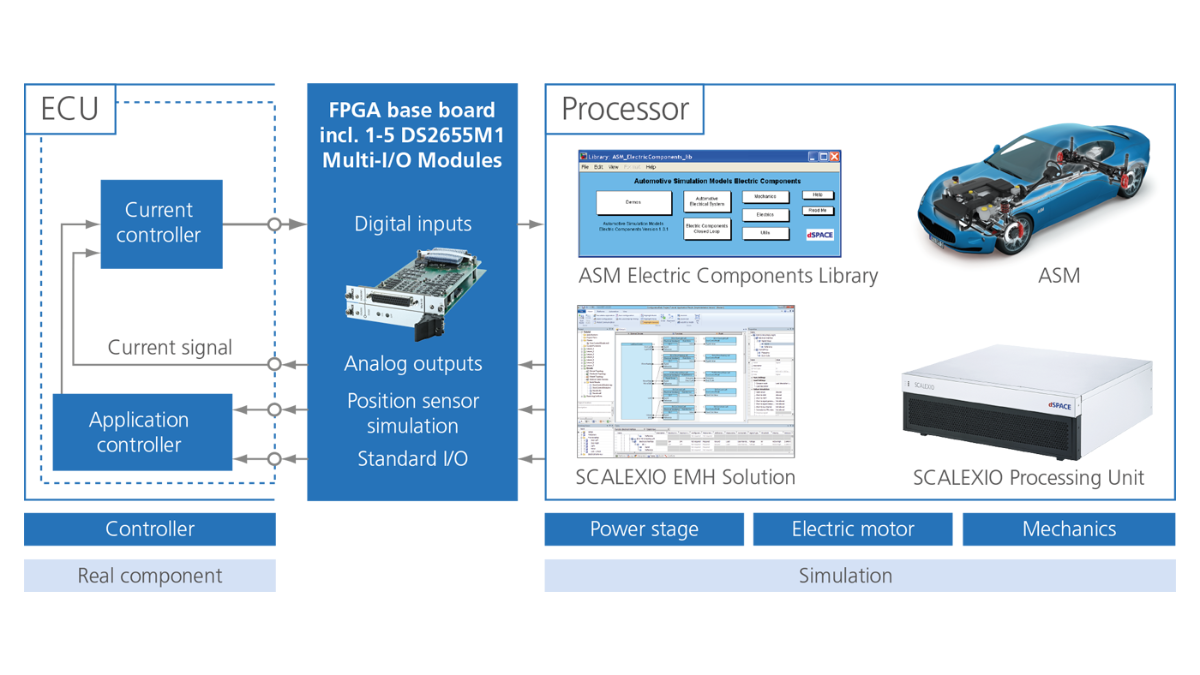

Processor-Based Simulation of Electric Drives
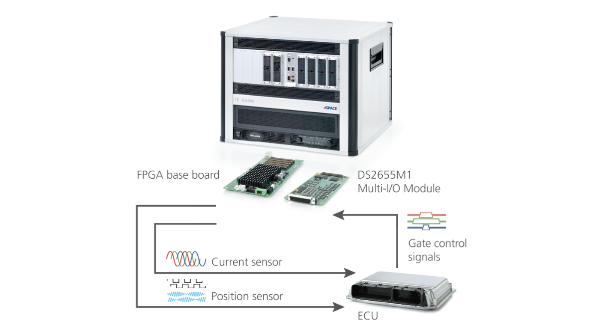
The SCALEXIO EMH Solution can be used for defining the I/O functions for the simulation of up to two electric drives. The required FPGA base board (DS6601, DS6602 or DS2655) is configured from within ConfigurationDesk. Thanks to the predefined function blocks, users do not have to program or generate FPGA code. The DS2655M1 and DS6651 Multi-I/O Modules as well as the integrated angular processing units (APUs) enable the use of high-resolution I/O to support applications in the areas of position sensor simulation (PSS) and pulse width modulation (PWM). The variable I/O channel mapping and the flexible support of up to five DS2655M1 or up to five DS6651 Multi-I/O Modules open up the hardware’s full potential. If the drive controller requires an enhanced simulation resolution, a seamless switch to FPGA-based simulation is possible without changing the hardware. The EMH Solution FPGA design includes four internal APUs running on the FPGA base board to calculate the local position. Furthermore, up to six master APUs can be referenced globally as position sources via IOCNET. Each of the position sensors can be configured for allocating one of the ten APUs as the position source.
Depending on the number of DS2655M1 modules, the available amount of I/O channels varies.
Main Functions for Position Sensor Simulation (PSS)
| Function | Description | I/O Requirements per Function | |
|---|---|---|---|
| Resolver Out | Simulation with configurable pole pair number, offset angle, transformer ratio. Excitation input signal delay. Output amplitude and phase error manipulation. | 2 |
Excitation: 1x Analog In Sin/Cos: 2x Analog Out |
| Sine Encoder Out | Simulation with configurable number of lines, output amplitude and DC offset | 2 | A,B, Index: 3x Analog Out Or1 6x Analog Out |
| Incremental Encoder Out | Simulation with configurable number of lines and offset angle | 2 | A,B, Index: 3x Digital (Out) Or1 6x Digital (Out) |
| Hall Encoder Out | Simulation with configurable pole pair number, offset angle, angle-dependent pulse activation/deactivation | 2 | A,B,C: 3x Digital (Out) Or1 6x Digital (Out) |
| Analog Wavetable Encoder Out | Output with freely designable analog shape format for 360 degrees with up to 16383 values and optional linear interpolation for intermediate values. Configurable number of waveforms per revolution. | 3 | 1x Analog Out |
|
Digital Wavetable Encoder Out |
Output with freely designable digital shape format for 360 degrees with up to 16383 values. Configurable number of waveforms per revolution. | 3 | 1x Digital (Out) |
Main Functions for Pulse Width Modulation (PWM)
| Function | Description | I/O Requirements per Function | |
|---|---|---|---|
| Six-Channel PWM In | Supporting duty cycle, period time, latch time and dead time2 measurement and configurable interrupt generation (latch-based measurement), oversampling, downsampling Optional external triggering Optional2 dead time violation interrupt generation | 2 |
Gates: 3x Digital (In) Or2 Optional ext. trigger: Optional latch pulse: 1x Digital (Out) |
| Single-Channel PWM In | Combined edge-based and latch-based measurement of duty cycle and frequency | 4 | 1x Digital (In) |
| Single-Channel PWM Out | PWM generation with variable frequency and duty cycle | 4 | 1x Digital (Out) |
Basic I/O Functions
| Function | Description | Number of Functions per FPGA Base Board | I/O Requirements per Function |
|---|---|---|---|
| Multi-Bit In | Standard digital input functionality for variable number of channels | 4 | 1-50 Digital (In) |
| Multi-Bit Out | Standard digital output functionality for variable number of channels | 4 | 1-50 Digital (Out) |
| Multi-Voltage In | Standard analog input functionality for variable number of channels | 4 | 1-25 Analog In |
| Multi-Voltage Out | Standard analog output functionality for variable number of channels | 4 | 1-25 Analog Out |
-
- View online
- Download
- SCALEXIO Modular real-time system for RCP and HIL applications
- ASM Electric Components Real-time models for automotive electric system and drive simulation
- Electrical Power Systems Simulation Package Easy real-time simulation of power electronics circuits developed with Simscape Electrical™ (Specialized Power Systems)
Drive innovation forward. Always on the pulse of technology development.
Subscribe to our expert knowledge. Learn from our successful project examples. Keep up to date on simulation and validation. Subscribe to/manage dSPACE direct and aerospace & defense now.