AC Motor Control Solution
Simple development of complex controls for energy-efficient electric drives
The AC Motor Control Solution lets you access the I/O functionalities of the DS1553 AC Motor Control Modules for the MicroAutoBox III to control electric engines and configure them with the utmost convenience.
- Access to the extended FPGA-based I/O functionalities for electric engine control of the MicroAutoBox III.
- Simple configuration of the functions in ConfigurationDesk and implementation of controllers in MATLAB®/Simulink®.
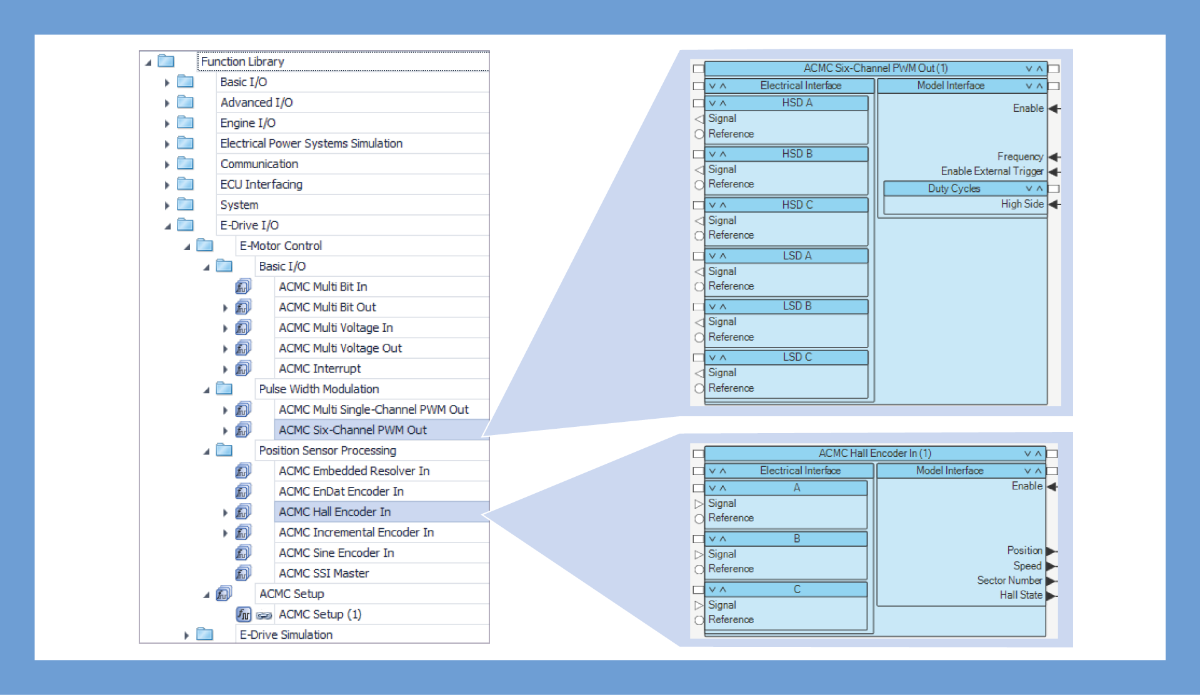
- Support of Hall sensor inputs, incremental encoders, resolvers, EnDat and SSI interfaces, and of various gate controls.
- Automatic calculation and extrapolation of the engine speed, position, and angle as well as the generation of triggers and interrupts.
The AC Motor Control Solution provides I/O functionalities specially for the processor-based control of electric drives. A MicroAutoBox III, which is equipped with a DS1514 and additionally with a DS1553, can cover this.

Use case example for an electric or a hybrid vehicle.
Application Fields
The control of electric motors plays an important role in almost all application areas, such as the automobile industry, robotics, or medical engineering. It helps adhere to the new, strict emissions standards and build upon more precise machines in the industrial environment.
Often, the control algorithm of an electric motor is the decisive factor in meeting customer requirements. However, the effort required to develop, implement, and validate the necessary control algorithms in conventional, usually inflexible tool chains is sometimes very high. The MicroAutoBox III variants equipped with a DS1514 FPGA Base Board, together with an I/O plug-on module for controlling various electric drives, form an ideal system for reducing this effort.
Benefits
The DS1553 offers I/O Interfaces for the user-programmable FPGA of MicroAutoBox III. The evaluation and processing of the signals communicated by sensor interfaces commonly used for electric motors, such as Hall, incremental encoder, resolver, EnDat, or SSI, is performed entirely on the processor via MATLAB®/Simulink® without the user having to program the FPGA. Ready-to-use Simulink blocks are also available for the generation of various synchronous PWM signals. The actual values of speed, position, and angle of the electric motor are calculated automatically. If sensor interfaces with low resolution, such as Hall sensors, are used, automatic extrapolation ensures higher sensor resolution and thus improves the quality of the position measurement. To detect the actual motor position already at startup, the Hall sensor interface is directly available. After one revolution of the electric motor, it is possible to switch to a sensor with higher resolution, such as the encoder interface. This procedure means that a permissible position of the motor and the optimum resolution are always accessible to the controller. Simulink-based controller models can be easily connected to the required I/O interfaces and downloaded to the MicroAutoBox III at the push of a button. The controller can be tested in a real environment with various sensors and actuators, and new strategies for motor control can be developed much faster than with conventional tool chains.
| Functionality | Description |
|---|---|
| General |
|
Drive innovation forward. Always on the pulse of technology development.
Subscribe to our expert knowledge. Learn from our successful project examples. Keep up to date on simulation and validation. Subscribe to/manage dSPACE direct and aerospace & defense now.