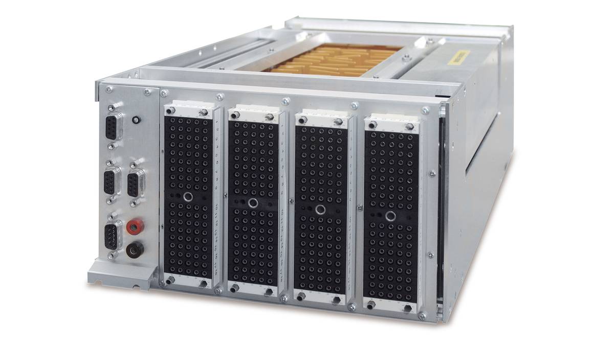
DS2680 I/O Unit
MultiCompact I/O unit for powertrain and vehicle dynamics scenarios
The DS2680 I/O Unit is a MultiCompact I/O unit for the SCALEXIO system that provides all the I/O channels required for the hardware-in-the-loop simulation of transmission or vehicle dynamics ECUs.
- 140 channels for extensive I/O functions
- Compact half 19" unit
- Provides all basic functionalities for HIL tests
Application Areas
The DS2680 I/O Unit is a MultiCompact I/O unit for the SCALEXIO system that provides all the I/O channels required for the hardware-in-the-loop simulation, e.g., of transmission or vehicle dynamics ECUs. Most of the I/O channels have a fixed function, i.e., they are dedicated analog or digital channels.
Key Benefits
Despite the compact design, the DS2680 offers a high number of predefined channels that include FIU functionalities. The described features in combination with the unit’s attractive price, makes the DS2680 the ideal tool for specific application scenarios.
Component Variants
The DS2680 is available with and without an integrated bus board. The integrated bus board provides two channels for each of the bus protocols LIN, CAN and FlexRay. If you need more or different bus channels, for example, four CAN channels, you can use a HighFlex bus board in addition or as an alternative.
I/O Functionality
The DS2680 provides 38 I/O functions that are supported by different I/O channels. The channels are defined and configured graphically with dSPACE ConfigurationDesk.
Analog In
- Voltage In
- Voltage Signal Capture
- Current In
- Triggered Current In
- Current Signal Capture
Analog Out
- Voltage Out
- Current Sink
- Wavetable Voltage Out
- Wavetable Current Sink
- Waveform Voltage Out
- Waveform Current Sink
- Angular Wavetable Voltage Out
Digital In
- Multi Bit In
- Trigger In
- PWM/PFM In
- Digital Pulse Capture
- SENT In
Digital Out
- Multi Bit Out
- PWM/PFM Out
- Digital Pulse Out
- Wavetable Digital Out
- Waveform Digital out
- Angular Wavetable Digital Out
- SENT Out
Engine Simulation
- Injection/Ignition Voltage In
- Injection/Ignition Current In
- Crank/Cam Voltage Out
- Crank/Cam Current Sink
- Crank/Cam Digital Out
- Knock Signal Out
- Lambda DCR
- Lambda NCCR
Resistor Simulation
- Resistance Out
- Potentiometer Out
Further Sensor Simulation
- Digital Incremental Encoder Out
- Wheelspeed Out
Testing Electrical Faults
The DS2680 includes a Failure Insertion Unit (FIU) for testing ECU behavior in the event of a fault. It can be used as a central FIU for the SCALEXIO system. Each channel has a failure routing unit (FRU) for switching the connection to the FIU via the failrails.
Real Loads
Substitute loads can be plugged onto the DS2680 internally if required. An exchangeable load board is available for you to mount different plug-on loads. Real loads or large substitute loads can be connected externally via the load connector provided for them.
| Parameters | Specification |
|---|---|
| Signal measurement |
|
| Signal generation |
|
| Special I/O channels |
|
| Voltage supply |
|
| Buses (Only for DS2680 with bus support) |
|
| Failure Insertion Unit |
|
| Internal communication interface |
|
| Physical size |
|
| Voltage supply |
|
| Typical power consumption |
|
-
- View online
- Download
- ConfigurationDesk Configuration and implementation software for dSPACE real-time hardware
- AutomationDesk Powerful test authoring and automation tool for HIL testing of ECUs
- Automotive Simulation Models Tool suite for simulating the engine, vehicle dynamics, electrical system, and traffic environment
- Fault Simulation dSPACE SCALEXIO offers a flexible license concept for fault simulation
Drive innovation forward. Always on the pulse of technology development.
Subscribe to our expert knowledge. Learn from our successful project examples. Keep up to date on simulation and validation. Subscribe to/manage dSPACE direct and aerospace & defense now.