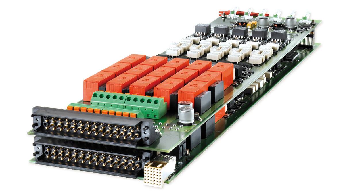
DS2601 Signal Measurement Board
HighFlex board for measuring ECU output signals
The DS2601 is used in SCALEXIO hardware-in-the-loop simulators. It provides current and voltage measurement during HIL tests of ECUs. The DS2601 can be equipped with onboard loads or external loads via a second connector.
- Channel bundling to increase current carrying capacity
- On-board failure routing unit
- Galvanically isolated channels
Application Area
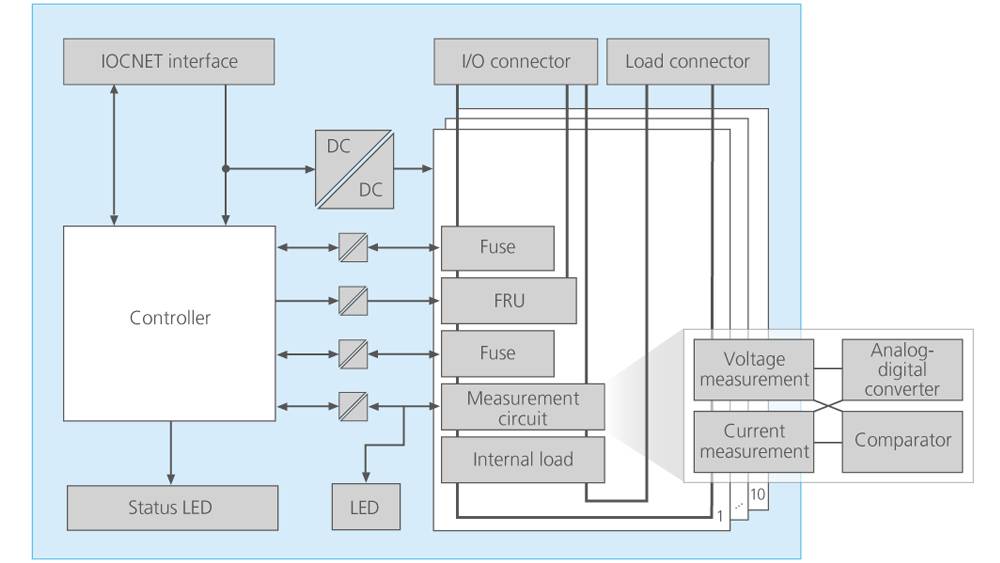
The DS2601 Signal Measurement Board measures ECU output signals and passes the measurement values to the real-time processor. Signal measurement can be time-triggered or event-triggered, and the execution of signal measurement can be voltage- or current-triggered.
Key Benefits
The DS2601 offers 10 versatile, software-configurable channels that can be used as analog or digital input for measuring voltage and current. The channels can be connected in parallel to increase the current-carrying capacity up to 80 A (RMS).
The board also includes an onboard failure routing unit.
I/O Functionality
The DS2601's input channels can connect analog as well as digital measurement units (analog-digital converters or comparators, respectively) to measure the current and voltage. For example, the measurement units can be combined to trigger analog current measurement if a specified voltage is exceeded. The channels are defined and configured in the ConfigurationDesk software.
The 10 channels on the DS2601 can be connected in parallel. This channel bundling increases the current-carrying capacity up to 80 A (RMS). ConfigurationDesk displays the bundled channels as one single I/O function. The DS2601 supports the use of loads for the ECU. You can either plug substitute loads onto the board itself or connect real loads via a cable harness to the externally accessible load connector.
| Parameter | Specification |
|---|---|
| General |
|
| Electrical capacity |
|
| Signal measurement (Flexible In 1) |
|
| Fault simulation |
|
| Electronic fuses |
|
| Internal communication interface |
|
| Physical size |
|
| Voltage supply |
|
| Typical power consumption |
|
-
- View online
- Download
- Fault Simulation dSPACE SCALEXIO offers a flexible license concept for fault simulation
- ConfigurationDesk Configuration and implementation software for dSPACE real-time hardware
Drive innovation forward. Always on the pulse of technology development.
Subscribe to our expert knowledge. Learn from our successful project examples. Keep up to date on simulation and validation. Subscribe to/manage dSPACE direct and aerospace & defense now.