MicroLabBox

Compact prototyping unit for the laboratory

MicroLabBox is an all-in-one development system for the laboratory that combines compact size and low system costs with high performance and versatility.

  • Intelligent Drilling

    Simulating extreme environmental conditions for control units

    Schlumberger Ltd.

    Read More

  • Fast Control for Three-Phase Synchronous Motors with an EnDat 2.2 Interface on MicroLabBox

    Rosenheim University of Applied Sciences

    Read More

  • Chain-Free Cycling

    Serial hybrid drive for bicycles
    Institut für Automatisierung und Informatik GmbH (IAI)

    Read More

  • Press Release: Paderborn, February 11, 2015:

    dSPACE has introduced a new, compact control system development platform for laboratory use, MicroLabBox, that offers high computing power and comprehensive functionalities. MicroLabBox makes creating, optimizing and testing controllers, and implementing data acquisition applications easy and cost-efficient for both industry and academia.

    Read more

  • Compact power in the lab

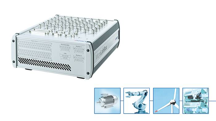
    With MicroLabBox, dSPACE introduces an entirely new system – a compact development system for laboratory use that is very powerful and versatile, despite its low system costs and small size. Over 100 channels of different I/O types and a combination of real-time processor and FPGA provide the versatility needed in research and development. This lets you implement control, test and data acquisition applications quickly, simply and costeffectively.

    Read more

Application Areas

MicroLabBox lets you set up your control, test or measurement applications quickly and easily, and helps you turn your new control concepts into reality. More than 100 I/O channels of different types make MicroLabBox a versatile system that can be used in mechatronic research and development areas, such as robotics, medical engineering, electric drives control, renewable energy, vehicle engineering, or aerospace.

Key Benefits

High computation power combined with very low I/O latencies provide great real-time performance. A programmable FPGA gives you a high degree of flexibility and lets you run even extremely fast control loops, as required in applications such as electric motor control or active noise and vibration cancellation.

MicroLabBox is supported by a comprehensive dSPACE software package, including, e.g., Real-Time Interface (RTI) for Simulink® for model-based I/O integration and the experiment software ControlDesk, which provides access to the real-time application during run time by means of graphical instruments.

MicroLabBox, top panel variant with spring-cage terminal blocks

Versatility through Connector Panel Variants 

MicroLabBox is available in three connector panel variants, offering different types and/or positions of the I/O connectors. The front panel variant provides Sub-D connectors at the front to access the connectors of the MicroLabBox when it is included in a stack of laboratory equipment or easily switch between wire harnesses. The top panel variant is available with two different connector types and is ideal for desk use.

Equipped with BNC and Sub-D connectors, the top panel MicroLabBox allows easy access to the analog I/O channels via probes that are typically used in laboratories to offer high analog signal quality. Additionally, a top panel variant with spring-cage terminal blocks, which are often used in industrial automation, is available. This means, signal connections can be changed very fast and conveniently by means of a common push-in and release mechanism of the clamp with a standard screwdriver. To make wiring and signal tracing as user-friendly as possible, all panel variants show the pinout information on the unit itself. The pinout information is also displayed in the I/O blocks of the implementation software Real-Time Interface (RTI).

Overview of MicroLabBox variants: Front-panel variant (left), Top-panel variant (right)


Parameter Specification 1 Specification 2 Specification 3
MicroLabBox Variants Front Panel Variant Top Panel Variant with BNC Connectors Top Panel Variant with Spring-Cage Terminal Blocks
Processor
  • Real-time processor
    • NXP (Freescale) QorlQ P5020, dual-core, 2 GHz 32 KB L1 data cache per core, 32 KB L1 instruction cache per core, 512 KB L2 cache per core, 2 MB L3 cache total
  • Host communication
    • NXP (Freescale) QorlQ P1011 800 MHz for communication with host PC
  • Memory
    • 1 GB DRAM 128 MB flash memory
  • Boot time
    • Autonomous booting of applications from flash (depending on application size), ~5 s for a 5 MB application
Interfaces
  • Host interface
    • Integrated Gigabit Ethernet host interface
  • Ethernet real- time I/O interface
    • Integrated low-latency Gigabit Ethernet I/O interface
  • USB interface
    • USB 2.0 interface for data logging ("flight recorder") and booting applications via USB mass storage device (max. 32 GB supported)
  • CAN interface
    • 2 CAN channels (partial networking supported)
  • Serial interface
    • 2 x UART (RS232/422/485) interface
  • LVDS interface
    • 1 x LVDS interface to connect with the Programmable Generic Interface PGI1
  • Programmable FPGA1)
    • Xilinx® Kintex®-7 XC7K325T FPGA
Analog input
  • Resolution and type
    • 8 14-bit channels, 10 Msps, differential; functionality: free running mode
    • 24 16-bit channels, 1 Msps, differential; functionality: single conversion and burst conversion mode with different trigger and interrupt options
  • Input voltage range
    • -10 ... 10 V
  • Resolution and type
    • 8 14-bit channels, 10 Msps, differential; functionality: free running mode
    • 24 16-bit channels, 1 Msps, differential; functionality: single conversion and burst conversion mode with different trigger and interrupt options
  • Input voltage range
    • -10 ... 10 V
  • Resolution and type
    • 8 14-bit channels, 10 Msps, differential; functionality: free running mode
    • 24 16-bit channels, 1 Msps, differential; functionality: single conversion and burst conversion mode with different trigger and interrupt options
  • Input voltage range
    • -10 ... 10 V
Analog output
  • Resolution and type
    • 16 16-bit channels, 1 Msps, settling time: 1 µs
  • Output voltage range
    • -10 ... 10 V
  • Output current
    • ± 8 mA
  • Resolution and type
    • 16 16-bit channels, 1 Msps, settling time: 1 µs
  • Output voltage range
    • -10 ... 10 V
  • Output current
    • ± 8 mA
  • Resolution and type
    • 16 16-bit channels, 1 Msps, settling time: 1 µs
  • Output voltage range
    • -10 ... 10 V
  • Output current
    • ± 8 mA
Digital I/O
  • 48 bidirectional channels, 2.5/3.3/5 V (single-ended); functionality: bit I/O, PWM generation and measurement (10 ns resolution), pulse generation and measurement (10 ns resolution), 4 x SPI Master 12 bidirectional channels (RS422/485 type) to connect sensors with differential interfaces
  • 48 bidirectional channels, 2.5/3.3/5 V (single-ended); functionality: bit I/O, PWM generation and measurement (10 ns resolution), pulse generation and measurement (10 ns resolution), 4 x SPI Master 12 bidirectional channels (RS422/485 type) to connect sensors with differential interfaces
  • 48 bidirectional channels, 2.5/3.3/5 V (single-ended); functionality: bit I/O, PWM generation and measurement (10 ns resolution), pulse generation and measurement (10 ns resolution), 4 x SPI Master 12 bidirectional channels (RS422/485 type) to connect sensors with differential interfaces
Electric motor control I/O functionality
  • Separate interfaces
    • 2 x Resolver interface
  • Functionality on digital I/O channels
    • 6 x Encoder sensor input
      2 x Hall sensor input
      2 x EnDat interface
      2 x SSI interface
      Synchronous multi-channel PWM
      Block commutational PWM
  • Sensor supply
    • 1 x 12 V, max. 3 W/250 mA (fixed) 1 x 2 ... 20 V, max. 1 W/200 mA (variable)
  • Feedback elements
    • Programmable buzzer
      Programmable status LEDs
  • Theft protection
    • Kensington® lock
  • Cooling
    • Active cooling (temperature-controlled fan)
  • Physical connections
    • 4 x Sub-D 50 I/O connectors
      4 x Sub-D 9 I/O connectors
      3 x RJ45 for Ethernet (host and I/O)
      USB Type A (for data logging)
      2 x 2 banana connectors for sensor supply Power supply
  • Separate interfaces
    • 2 x Resolver interface
  • Functionality on digital I/O channels
    • 6 x Encoder sensor input
      2 x Hall sensor input
      2 x EnDat interface
      2 x SSI interface
      Synchronous multi-channel PWM
      Block commutational PWM
  • Sensor supply
    • 1 x 12 V, max. 3 W/250 mA (fixed) 1 x 2 ... 20 V, max. 1 W/200 mA (variable)
  • Feedback elements
    • Programmable buzzer
      Programmable status LEDs
  • Theft protection
    • Kensington® lock
  • Cooling
    • Active cooling (temperature-controlled fan)
  • Physical connections
    • 2 x Sub-D 50 I/O connectors 48 x BNC I/O connectors
      4 x Sub-D 9 I/O connectors
      3 x RJ45 for Ethernet (host and I/O)
      USB Type A (for data logging)
      2 x 2 banana connectors for sensor supply Power supply
  • Separate interfaces
    • 2 x Resolver interface
  • Functionality on digital I/O channels
    • 6 x Encoder sensor input
      2 x Hall sensor input
      2 x EnDat interface
      2 x SSI interface
      Synchronous multi-channel PWM
      Block commutational PWM
  • Sensor supply
    • 1 x 12 V, max. 3 W/250 mA (fixed) 1 x 2 ... 20 V, max. 1 W/200 mA (variable)
  • Feedback elements
    • Programmable buzzer
      Programmable status LEDs
  • Theft protection
    • Kensington® lock
  • Cooling
    • Active cooling (temperature-controlled fan)
  • Physical connections
    • 2 x Sub-D 9 I/O connectors 27 x spring-cage terminal block connectors with 8 pins each 3 x RJ45 for Ethernet (host and I/O)
      USB Type A (for data logging)
      2 x 2 banana connectors for sensor supply Power supply

  • MicroLabBox Product Information, PDF, English, 2145 KB
More Information Related Topics Documentation Contact Information

Drive innovation forward. Always on the pulse of technology development.

Subscribe to our expert knowledge. Learn from our successful project examples. Keep up to date on simulation and validation. Subscribe to/manage dSPACE direct and aerospace & defense now.

Enable form call

At this point, an input form from Click Dimensions is integrated. This enables us to process your newsletter subscription. The form is currently hidden due to your privacy settings for our website.

External input form

By activating the input form, you consent to personal data being transmitted to Click Dimensions within the EU, in the USA, Canada or Australia. More on this in our privacy policy.