Compact. Powerful. MicroLabBox II. Your development and test system for rapid control prototyping and hardware-in-the-loop applications.
Easy transition
From offline simulation in Simulink® to execution on the MicroLabBox II.
Ready-to-use I/O functions
Comprehensive set of I/O libraries provided by dSPACE.
Communication interfaces
Bus & network interfaces incl. 10 GBit/s Ethernet, CAN FD, LIN.
Powerful CPU & large FPGA
Geared up for what is ahead of you: Fast control loops, complex models and much more.
What is MicroLabBox II?
As the evolution of the well established MicroLabBox I, the MicroLabBox II is a compact laboratory system for rapid control prototyping and hardware-in-the-loop (HIL) applications that combines compact size and cost-effectiveness with high performance and versatility.
Its high-performance quad core processor can easily run demanding Simulink® models, e.g., for the simulation of electric motors. Its extensive set of I/O interfaces every single reqquirement of control or test engineers who want to prototype their algorithms.
Furthermore, the MicroLabBox II provides a user-programmable FPGA for even faster control loops or the most demanding and accurate simulation models.
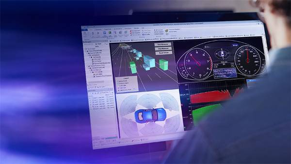
Thanks to the dSPACE experiment software, ControlDesk, model signals can be accessed for visualization and measurement purposes without additional effort. Model parameters can be calibrated during run time without recompiling the application.
Application Areas
The MicroLabBox II lets you set up your control, test, or measurement applications quickly and easily, and helps you turn your individual concepts into reality. More than 100 I/O channels of different types make the MicroLabBox II a versatile system that can not only be used in mechatronics research and development areas, but also for all kinds of testing purposes such as:
- Electric drives development
- Power electronics development
- Research & education in academia
- Renewable energy
- Aerospace
- Robotics
- Medical engineering


Wide Variety of I/O Functions
As the latest generation of the well established MicroLabBox series, the MicroLabBox II comes with a wide variety of I/O functions that make it easy to connect existing models to hardware channels.
Included I/O functions:
- Voltage in/ voltage out
- PWM inputs/ PWM outputs
- Voltage signal capture, digital pulse capture
- Waveform out, digital pulse out
- UART, I²C1, SPI1
- CAN FD, LIN
- Ethernet
- XCP on Ethernet/ CAN
... and many more.
1 Planned for later releases
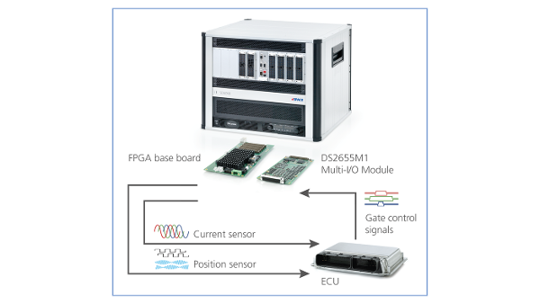
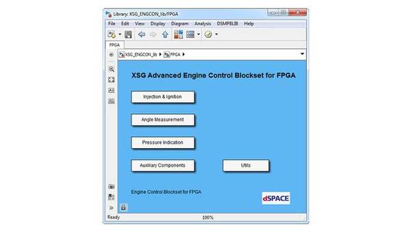
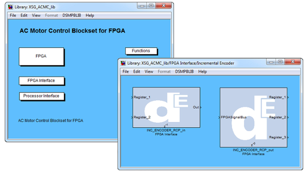
For E-Mobility applications, dSPACE offers a comprehensive set of ready-to-use functions for processor-based e-motor control applications including field-oriented control with support for sine-, hall-, incremental encoders or resolvers.
Libraries for FPGA based e-motor control applications that allow to reach even faster turn-around times are also available.
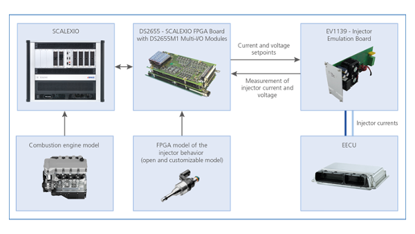
For hardware-in-the-loop applications, dSPACE also provides libraries for processor-based and FPGA-based e-motor and power electronics simulation.
User-Programmable AMD® Kintex® UltraScale+ FPGA
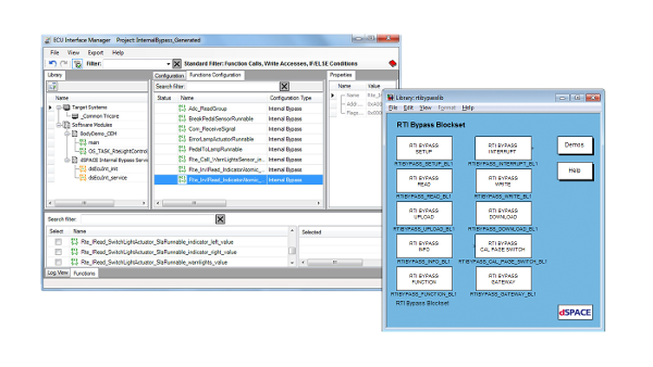
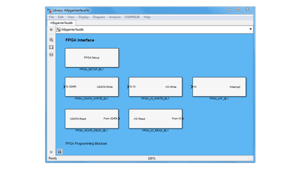
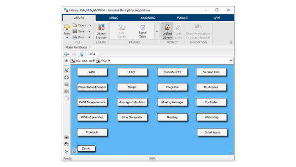
Using the dSPACE-provided I/O functions for fast prototyping implementations, you can execute your own model on the MicroLabBox processor or you can create your own FPGA-application, either model-based or written in VHDL. dSPACE also provides a variety of libraries for model-based FPGA development to benefit from the speed of an FPGA without having to deal with the difficulties of FPGA design.
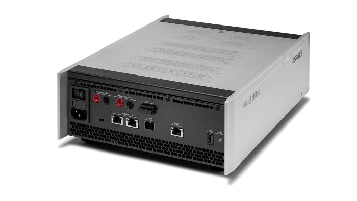
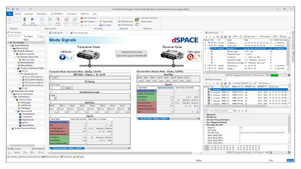
Bus & Network Interfaces
The MicroLabBox II provides up to 4 CAN FD channels with signal improvement capability (SIC) as well as up to 4 LIN channels. The two standard Ethernet ports support data rates of up to 10 GBit/s and can also be used for automotive Ethernet when using a media converter.

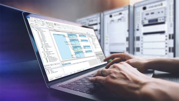
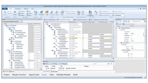
Well-Established dSPACE Tool Chain
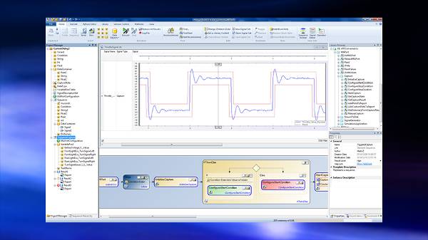
The corresponding software ConfigurationDesk is used to easily connect an existing Simulink® model to the hardware interfaces of the MicroLabBox II. As soon as the interfaces are specified and configured, the execution of your model is just one click away.
ConfigurationDesk not only lets you use Simulink® models, but it also supports container formats like SIC and FMU.
Once the application is running, ControlDesk can be used to visualize, measure, and even adjust model variables during run time. The MicroLabBox II USB port can also be used for data logging.
Technical details & variants

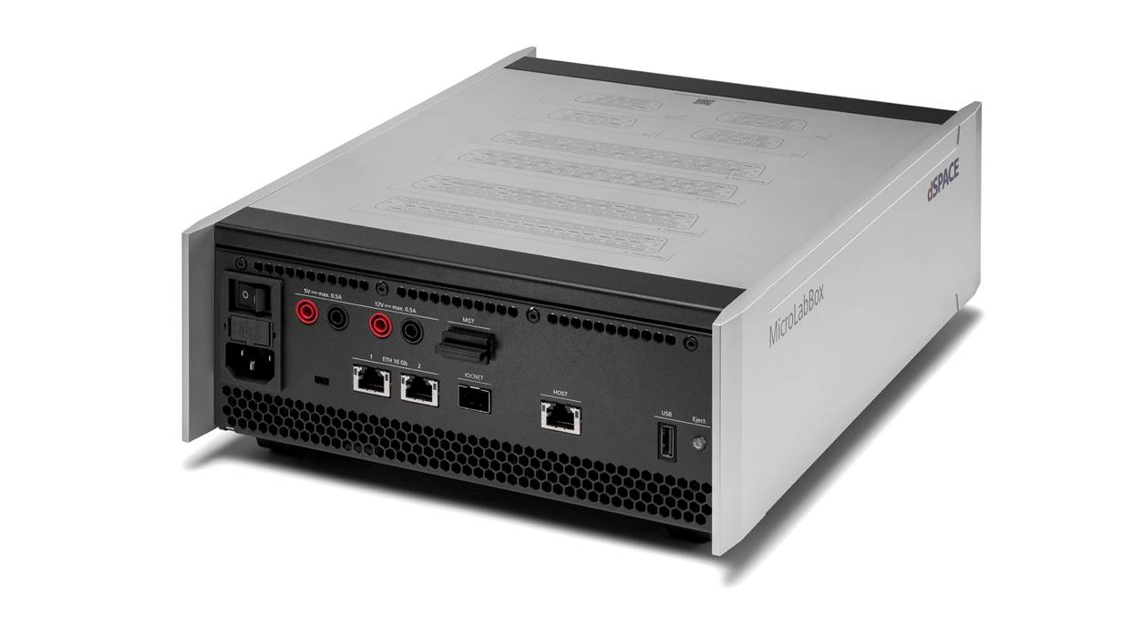
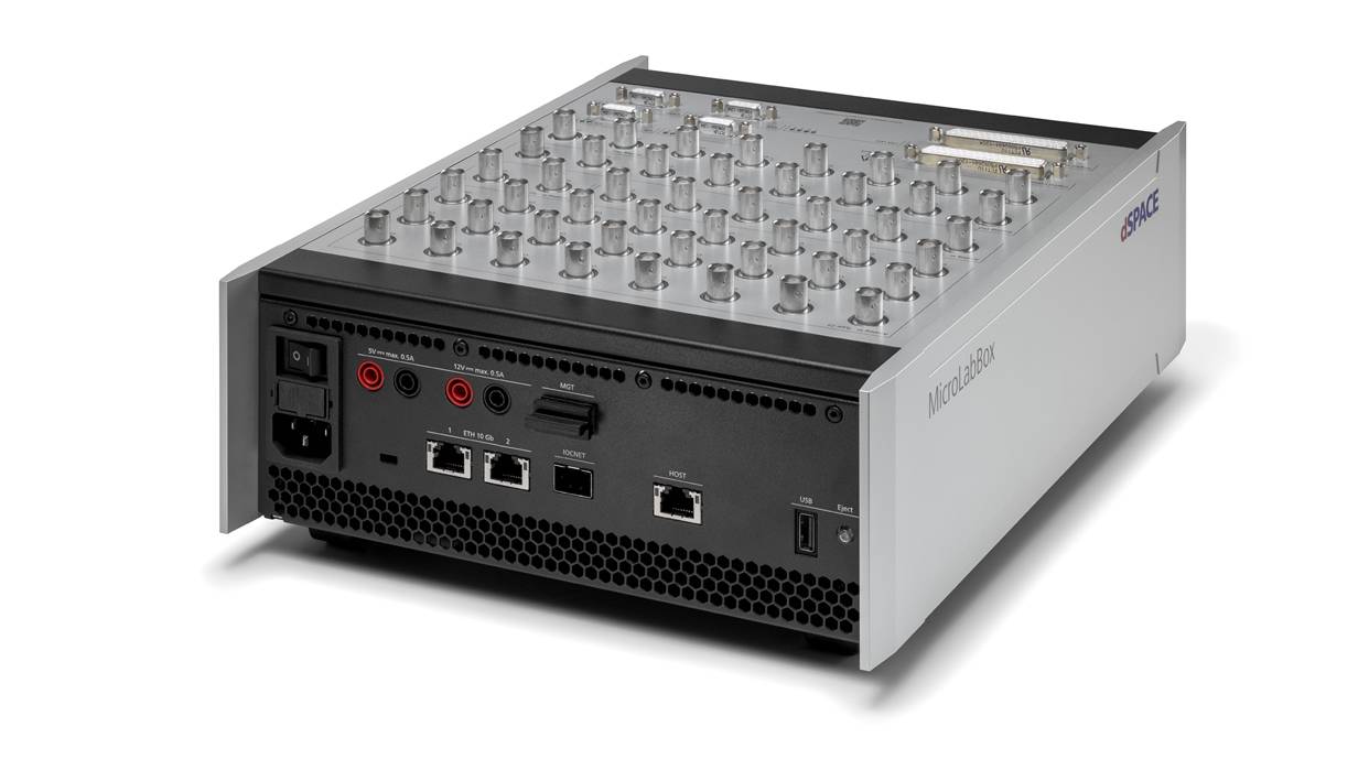
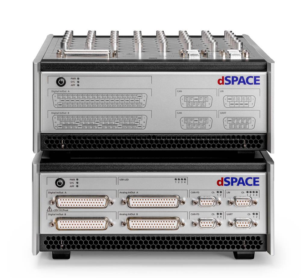
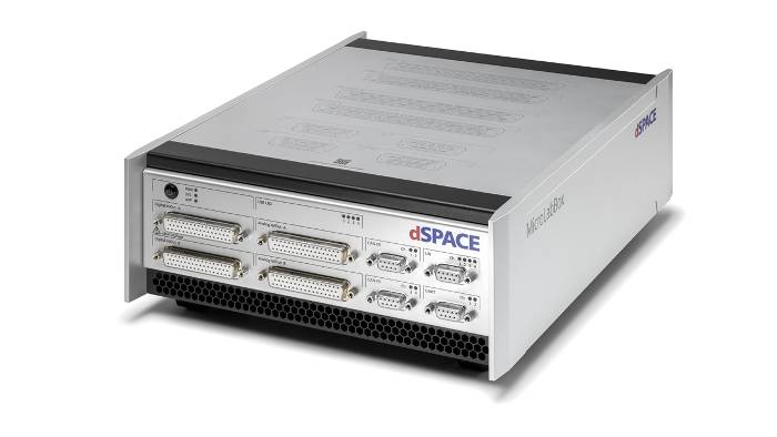
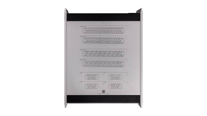
Front Panel - Simply Stack
The front-panel variant is especially well suited if the MicroLabBox II is installed in a cabinet, as connectors are accessible from the front.
Due to the arrangement of the connectors on the front side, it is possible to stack several MicroLabBoxes on top of each other.
In addition, transfer modules can be connected with little effort in order to quickly and easily plug in individual cables using spring cage terminals without having to assemble connectors beforehand.

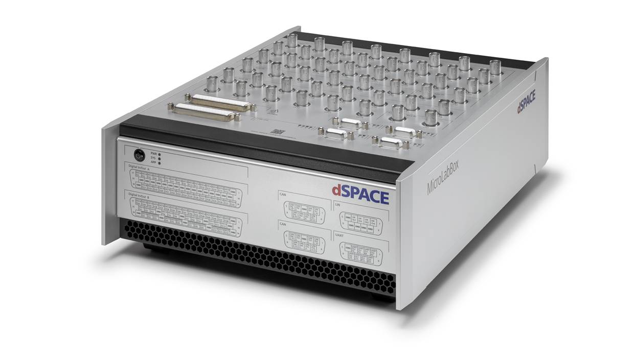
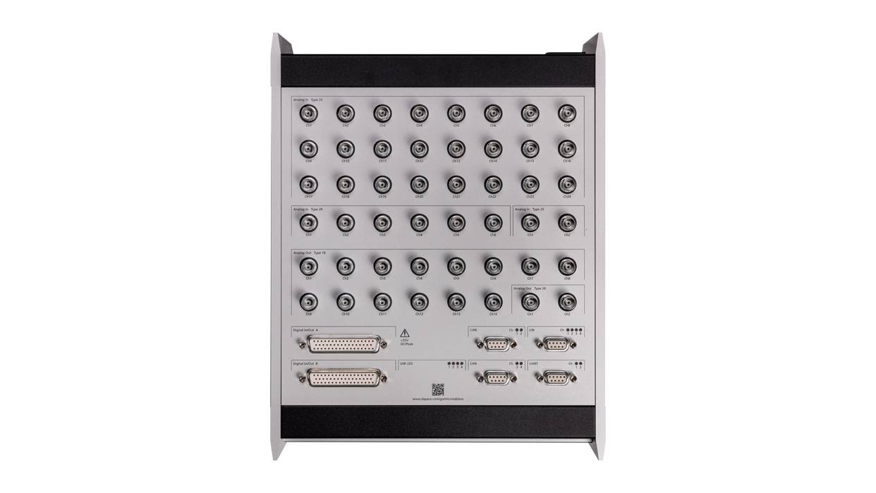
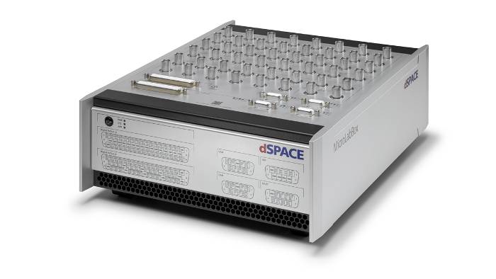
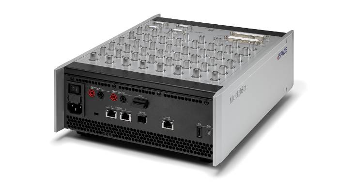
Top Panel - Customized Signals
The top panel variant uses BNC connectors for high signal integrity and allows easy connection and disconnection of individual signals.
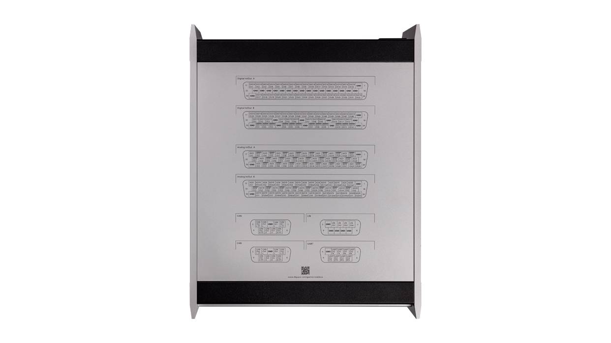
For both versions, the pin assignment of the individual connectors is printed on the housing for quick location.
Apart from the different arrangement of the connectors, the two versions are technically identical.

Advanced Feature Package
The Advanced Feature Package unlocks additional hardware and software features for more demanding use cases.
With this package, you can use 4 processor cores in total, 2 additional CAN FD channels, 4 LIN channels and IOCNET for I/O extension.
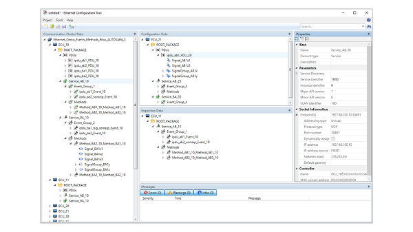
Furthermore, it enables the use of a second 10 Gb Ethernet interface and it allows you to use both interfaces with the Ethernet configuration package, e. g. to implement SOME/IP or use IEEE 802.1ad.
Our sales team is happy to advice you in chosing the rigth variant for your application!
Technical details
| Parameters | MicroLabBox II | MicroLabBox II with Advanced Feature Package | |
| Processor |
|
|
|
| FPGA |
|
||
| Communication interfaces |
|
|
|
| Analog input |
|
||
| Analog output |
|
||
| Digital I/O |
|
||
| Angular Processing Unit |
|
||
| Electric Motor Control I/O Functionality |
Functionality on digital I/O channels:
|
||
| Sensor supply |
|
||
| User feedback |
|
||
| Theft protection | Kensington® lock | ||
| Power supply & cooling |
|
||
| Operating temperature range | 0 °C … +50 °C (+32 °F … +122 °F) | ||
| Certifications |
|
||
| Parameters | Front Panel | Top Panel | |
| Connectors |
|
|
|
| Dimensions |
|
|
|
| Weight | 6.1 kg (13.5 lb) | 6.3 kg (13.9 lb) | |
1 Planned for later releases
Required product
Optional products

E-Mobility applications

Hardware Interfaces
The MicroLabBox II provides hardware interfaces for Hall-, Incremental-, Sinus Encoder, Resolver, SSI and EnDat that can be expanded with the Xilinx Aurora optical interface.
Furthermore, the MicroLabBox II has an integrated sensor supply with 5 V and 12 V banana plug outputs. Therefore, there is no extra power supply necessary which leaves more room on the developer's desk.
Leveraging the benefits of FPGA technology
For the high switching frequencies of state-of-the-art inverter controllers, processor based approaches are often not fast enough. Therefore, dSPACE offers FPGA libraries to enable you to easily built FPGA-based controllers without requiring expert knowledge. The same principal applies to simulation models, where FPGA technology allows for highest dynamics and precision.

Hardware-in-the-Loop (HIL) Applications
Like all dSPACE real-time systems/ platforms, the MicroLabBox II can be used for a variety of HIL applications. Due to its compact form factor, it is an optimal choice for a bench top simulator, that still provides enough processing power and I/O for large models.